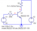
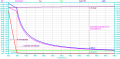
To maintain the transistor in saturation region

Status
Not open for further replies.

LvW

Joined Jun 13, 2013
2,031
I do not see what you mean. It seems that you are looking at this one way while I am looking at it from a different perspective.

Is the following statement true or false:
"The collector current is always equal to the Beta times the base emitter current".

How many times have we seen Ic=Ib*Beta? It must have been a lot, yet sometimes we see less iC than other times. So what is going on here?

What is going on is the action of the collector base diode is reducing the overall Beta as the collector voltage falls and starts to make the transistor enter what we call CE saturation. Thus, we actually have TWO (or more) different Beta's to consider. We have the major Beta spec of the transistor, which could be 100 or so, and we have the decreased Beta which comes from the forward biasing of the collector base diode.
For perfectly linear operation, we usually use the spec of 100, but for saturation we often (but not always) use a value of 10.

Now I ask the question again:
Is the following statement true or false:
"The collector current is always equal to the Beta times the base emitter current".
Of course, I can and will answer your question - based on the example as given in the question:
* From the given values we can (roughly) find the current Ib going into the base node (Ib=21µA).

* From the rule of thumb for saturation I select a current ratio Ic,sat/Ib=10
(Remark: I never would use the term "beta" for this ratio, but thats another story).

* Question to you: Will the collector current be Ic=10*21=210 µA?
* My answer: No. That means: The collector current is NOT equal to the assumed factor times the base emitter current".
(The actual "beta" is unknown - until we measure it).

That`s all I wanted to make clear.
I did not say that you were wrong - I know what you mean. However, in my view your sentence ( "This means that with 21ua into the base you calculate the collector current") sounds a bit misleading in the context of the question under discussion.
Sorry - but I do not hesitate to say: It is wrong!
We simply cannot "calculate the collector current" because we have not the actual "beta" - have you?

What we can and must do is the following: We are using the assumed value of Ic/Ib=10 to find the corresponding Rc value which allows saturation. And because we know that - in reality - Ic will be much larger than 10*21µA (due to the safety margin) we can be sure to be in saturation.

Am I wrong?
 
Last edited:

WBahn

Joined Mar 31, 2012
32,993
Of course, I can and will answer your question - based on the example as given in the question:
* From the given values we can (roughly) find the current Ib going into the base node (Ib=21µA).

* From the rule of thumb for saturation I select a current ratio Ic,sat/Ib=10
(Remark: I never would use the term "beta" for this ratio, but thats another story).

* Question to you: Will the collector current be Ic=10*21=210 µA?
* My answer: No. That means: The collector current is NOT equal to the assumed factor times the base emitter current".
(The actual "beta" is unknown - until we measure it).

That`s all I wanted to make clear.
I did not say that you were wrong - I know what you mean. However, in my view your sentence ( "This means that with 21ua into the base you calculate the collector current") sounds a bit misleading in the context of the question under discussion.
Sorry - but I do not hesitate to say: It is wrong!
We simply cannot "calculate the collector current" because we have not the actual "beta" - have you?

What we can and must do is the following: We are using the assumed value of Ic/Ib=10 to find the corresponding Rc value which allows saturation. And because we know that - in reality - Ic will be much larger than 10*21µA (due to the safety margin) we can be sure to be in saturation.

Am I wrong?
No. But....

We have to keep in mind the context that the TS is working in.

It's like in introductory physics when, at first, there is no such thing as friction. Then, when there is friction, there is a single coefficient of friction that is a constant. Then there are two constant coefficients, one static and one dynamic. That's usually how far they get in an intro course, even though friction in the real world is a LOT more complicated. When working with a student taking an intro physics course, if they are at the stage of working in a friction-free universe, are we really doing them an good by insisting that they take the difference between static and dynamic friction into account? Or should we operate in the universe they are currently in, confident that they will move closer to our universe as they progress through their journey?

The same is true here. Students just being introduced to diodes and transistors almost always use extremely simply constant or piecewise-linear models. The purpose is to introduce the gross behavior while keeping it simple enough that the focus can be on learning how to think about and apply those behaviors when analyzing and designing simple circuits.

I've looked at my remaining intro electronics books and, as expected, each author has taken a slightly different approach to this. But one of them is pretty close to what the author of the TS's textbook appears to be doing, which is to start off with an idealized transistor model in which the transistor has a ß in the active region that is constant right up to the point of saturation at Vcesat and then Vcesat is constant in saturation all the way down to cutoff. This is comparable to the ideal diode model that has a fixed forward voltage when conducting. There is nothing fundamentally wrong with using this model as an introduction and, indeed, even using it for "real world" design and analysis, provided its limitations are honored. At the first-exposure point, however, those limitations are often ignored for the time being.

So, consistent with the point in the TS's journey, as dictated by their text, they are looking for the magical point at which the collector current in the active region with the full active-region ß intersects the vertical collector-emitter voltage line in saturation. That this magical point doesn't actually exist in a real device, and how to deal with that, is something that they will get to down the road.

The end result is that we need to grit our teeth and bear it and try to restrict ourselves to the universe that is currently visible to the TS -- and I'm as guilty as anyone else of not always being able to do that.
 

LvW

Joined Jun 13, 2013
2,031
We have to keep in mind the context that the TS is working in.
.....................
I can agree to everything you wrote in your contribution.

Nevertheless, to make my concern clear I repeat what I wrote in my answer to MrAl:

"However, in my view your sentence ( "This means that with 21ua into the base you calculate the collector current") sounds a bit misleading in the context of the question under discussion."

I think, the quoted sentence is really misleading (even wrong) because the actual collector current will be unknown (neither 21µA*10 nor 21µA*100).

I think that if the TS is to work with the rule of thumb (10*Ib), then you have to explain the meaning and background to him. Only then can he understand why we calculate the resistance Rc required for saturation with a small - fictitious (!) -collector current (210µA).
The actual current Ic is not known, but it will be definitely greater than 210µA, which ensures saturation.
That was actually all I wanted to clarify.

In this context, I remember Einstein: "Everything should be made as simple as possible, but not simpler."
(My interpretation: As simple as possible, but not misleading or wrong)
 
Last edited:

WBahn

Joined Mar 31, 2012
32,993
I can agree to everything you wrote in your contribution.

Nevertheless, to make my concern clear I repeat what I wrote in my answer to MrAl:

"However, in my view your sentence ( "This means that with 21ua into the base you calculate the collector current") sounds a bit misleading in the context of the question under discussion."

I think, the quoted sentence is really misleading (even wrong) because the actual collector current will be unknown (neither 21µA*10 nor 21µA*100).

I think that if the TS is to work with the rule of thumb (10*Ib), then you have to explain the meaning and background to him. Only then can he understand why we calculate the resistance Rc required for saturation with a small - fictitious (!) -collector current (210µA).
The actual current Ic is not known, but it will be definitely greater than 210µA, which ensures saturation.
That was actually all I wanted to clarify.

In this context, I remember Einstein: "Everything should be made as simple as possible, but not simpler."
(My interpretation: As simple as possible, but not misleading or wrong)
In THIS problem, given the additional information that the TS provided regarding the text up to this point, the (highly simplified and not too realistic yet) model that he is using (and expected to use) has ß=100 right up to the magic point where Vce = Vcesat.

It doesn't matter how unrealistic that is in the real world, that is the model that this problem, in this text, is expecting him to use at this point.
 

LvW

Joined Jun 13, 2013
2,031
In THIS problem, given the additional information that the TS provided regarding the text up to this point, the (highly simplified and not too realistic yet) model that he is using (and expected to use) has ß=100 right up to the magic point where Vce = Vcesat.

It doesn't matter how unrealistic that is in the real world, that is the model that this problem, in this text, is expecting him to use at this point.
I would like to repeat that I am solely concerned with TS's understanding of the state of saturation.
And I was not sure - even after his 2nd contribution - that he understood the meaning and background of the estimate (rule of thumb) with Ib*10, because his final question was:

"I am little confused if the IB should be less than 21uA or more than 21uA, if it has to be more than 21uA then the Rc will have a maximum value not a minimum value."

My answer was only intended to clarify this question. But I don`t know if I was succesful.
 
Last edited:

MrAl

Joined Jun 17, 2014
13,728
Of course, I can and will answer your question - based on the example as given in the question:
* From the given values we can (roughly) find the current Ib going into the base node (Ib=21µA).

* From the rule of thumb for saturation I select a current ratio Ic,sat/Ib=10
(Remark: I never would use the term "beta" for this ratio, but thats another story).

* Question to you: Will the collector current be Ic=10*21=210 µA?
* My answer: No. That means: The collector current is NOT equal to the assumed factor times the base emitter current".
(The actual "beta" is unknown - until we measure it).

That`s all I wanted to make clear.
I did not say that you were wrong - I know what you mean. However, in my view your sentence ( "This means that with 21ua into the base you calculate the collector current") sounds a bit misleading in the context of the question under discussion.
Sorry - but I do not hesitate to say: It is wrong!
We simply cannot "calculate the collector current" because we have not the actual "beta" - have you?

What we can and must do is the following: We are using the assumed value of Ic/Ib=10 to find the corresponding Rc value which allows saturation. And because we know that - in reality - Ic will be much larger than 10*21µA (due to the safety margin) we can be sure to be in saturation.

Am I wrong?
Hello again,

I think that's the way we look at it. But you are making the same point I am. When you say your answer is NO to the question of if Ic=10*21ua=210ua, you may still be wrong, right? It COULD be just that, 210ua. So answering NO is only good when it does not work out. In most cases it probably won't be that though so answering NO is not that bad really we just have to make that one exception.

To explain it, we can say that when we estimate the Beta to be 10 we are using a constraint, not an absolute calculation.
A constraint is a limit that is imposed, not a direct equality. In most cases as you say "NO" it will not be 10, but we don't need it to be that anyway as you noted as well. We just need some constraint so we can proceed with some kind of reasonable calculation.

This estimate of Beta tells us what WOULD happen if the device behaved in an ideal way.
The constraint tells us what the device allows to happen in reality, or what we need to happen in reality.
We still call it the Beta though because it gives us the proper equation just the same. It's just a limit not an absolute.
This gives us the maximum collector current the transistor can pass:
Ic=Beta*Ib
Ic=10*21ua
Ic=210ua

and since Beta was an estimate, Ic is also an estimate, but it also gives us a constraint as the max collector current that would be seen as in:
"If the collector current is greater than or equal to 210ua, then the transistor is in saturation."
This also assumes a collector resistor that makes the CE voltage low enough to be considered in saturation, and that voltage may also be an estimate.

So Beta=10 should be looked at as a constraint not an absolute value. It gives us the maximum collector current the transistor can provide with a given base current. We still can call it a Beta because it still gives us a collector current to work with, even though that may not turn out to be the exact collector current in real life. We still multiply the base current times the Beta at some point in order to proceed anyway, which is what we always do with any Beta.
 

MrAl

Joined Jun 17, 2014
13,728
I would like to repeat that I am solely concerned with TS's understanding of the state of saturation.
And I was not sure - even after his 2nd contribution - that he understood the meaning and background of the estimate (rule of thumb) with Ib*10, because his final question was:

"I am little confused if the IB should be less than 21uA or more than 21uA, if it has to be more than 21uA then the Rc will have a maximum value not a minimum value."

My answer was only intended to clarify this question. But I don`t know if I was succesful.
Hi again,

If you want to be sure, then the only way to describe saturation is when the collector to base voltage drops lower than the base to emitter voltage, or maybe better: when the collector to base diode starts to conduct current in the forward direction. That conduction then steals some of the base current that would normally flow base to emitter, and that makes the Beta look lower, and it can end up looking much lower. We use a value of 10 in most cases, but I think the range is 5 to 20 or something depending on the type of transistor.

If like this better we can do this. We can call this the "Assumed Beta". That's "Assbeta" for short (ha ha).
Ok without joking, maybe Abeta or something. More traditionally "Forced Beta".

Because this may be an introductory course problem, they may actually want the student to use Beta=100 even when in saturation. This is what is done sometimes in these simpler courses.
 

LvW

Joined Jun 13, 2013
2,031
So Beta=10 should be looked at as a constraint not an absolute value. It gives us the maximum collector current the transistor can provide with a given base current. We still can call it a Beta because it still gives us a collector current to work with, even though that may not turn out to be the exact collector current in real life. We still multiply the base current times the Beta at some point in order to proceed anyway, which is what we always do with any Beta.
Hi again,
I am sure that all of us discussing this here are aware of the “secrets” of BJT saturation and the background to the estimated safety margin. No doubt about it.
As I can see it, the main problem is explaining the situation to a beginner using the right and correct words for a good understanding.
And in this context, the collector current deserves a special consideration.

Using the relationship Ic=B*Ib (in the example: B=10), we determine the value of a fictitious and much too small current (which will not flow at all) – only for the purpose to calculate a resistance Rc which, with the much larger current in reality, makes the product Ic*Rc so large that saturation is guaranteed despite unknown tolerances. Correct?

And with respect to the above I had some doubts if the TS could understand the correct meaning of the following statement:
"This means that with 21ua into the base you calculate the collector current" .

In this context, my question: What about the first two sentences in the text as quoted above?
"So Beta=10 .....gives us the maximum collector current the transistor can provide with a given base current"

Again: It is my only concern to explain the state of saturation (and the coresponding calculations) to the TS in an understandable way.
(But I know - and of course accept - that there will be different ways and methods of doing this).
 

MrAl

Joined Jun 17, 2014
13,728
Hi again,
I am sure that all of us discussing this here are aware of the “secrets” of BJT saturation and the background to the estimated safety margin. No doubt about it.
As I can see it, the main problem is explaining the situation to a beginner using the right and correct words for a good understanding.
And in this context, the collector current deserves a special consideration.

Using the relationship Ic=B*Ib (in the example: B=10), we determine the value of a fictitious and much too small current (which will not flow at all) – only for the purpose to calculate a resistance Rc which, with the much larger current in reality, makes the product Ic*Rc so large that saturation is guaranteed despite unknown tolerances. Correct?

And with respect to the above I had some doubts if the TS could understand the correct meaning of the following statement:
"This means that with 21ua into the base you calculate the collector current" .

In this context, my question: What about the first two sentences in the text as quoted above?
"So Beta=10 .....gives us the maximum collector current the transistor can provide with a given base current"

Again: It is my only concern to explain the state of saturation (and the coresponding calculations) to the TS in an understandable way.
(But I know - and of course accept - that there will be different ways and methods of doing this).
Hi,

Well what would you recommend as the best way to convey the required information?

I would think that for the simple circuit with collector resistor Rc:
(Vcc-Ib*10*Rc) <= 0.5v
might be good enough.
We might talk about the 0.5v spec as a variable depending on the quality of the transistor, or just mention that in passing.
 

LvW

Joined Jun 13, 2013
2,031
Hi,

Well what would you recommend as the best way to convey the required information?

I would think that for the simple circuit with collector resistor Rc:
(Vcc-Ib*10*Rc) <= 0.5v
might be good enough.
We might talk about the 0.5v spec as a variable depending on the quality of the transistor, or just mention that in passing.
Yes, because the factor 10 is freely selected (can be 5 or 15) it is of less importance if the right side is 0.5 or 0.2 volts.
 

MrAl

Joined Jun 17, 2014
13,728
Yes, because the factor 10 is freely selected (can be 5 or 15) it is of less importance if the right side is 0.5 or 0.2 volts.
Hi,

Maybe you can elaborate a little on that. We have to pick one, either 5, 10, or 15. We go with 10 for the most part.
 

LvW

Joined Jun 13, 2013
2,031
Hi,
Maybe you can elaborate a little on that. We have to pick one, either 5, 10, or 15. We go with 10 for the most part.
So - you want a kind of verification for this "rule of thumb"?
I think that the factor Ic,sat/Ib to be selected for calculation depends on the specific application - in particular the used transistor type and the specified range of values for the parameter h_FE.
In this context, we should be aware that such a calculation for ensuring saturation is only applicable if we use a relatively large switching voltage (Vs>>Vbe) with series resistance Rs between Vs and the base node.
For small switching voltages in the range (0.7...0.8) volts it doesn`t help too much to calculate with a specific value for the current Ib.
 

MrAl

Joined Jun 17, 2014
13,728
So - you want a kind of verification for this "rule of thumb"?
I think that the factor Ic,sat/Ib to be selected for calculation depends on the specific application - in particular the used transistor type and the specified range of values for the parameter h_FE.
In this context, we should be aware that such a calculation for ensuring saturation is only applicable if we use a relatively large switching voltage (Vs>>Vbe) with series resistance Rs between Vs and the base node.
For small switching voltages in the range (0.7...0.8) volts it doesn`t help too much to calculate with a specific value for the current Ib.
Hi,

Well now you are bringing another variable into the mix. That's ok, but then what you should do is prepare a semi formal text explanation possibly with a schematic to hand to the student. They can then ask questions and you can answer them. That would help the most I would think if you want to help them.

In the whole of my experience, I've used a lot more complex drive circuits where Beta or forced Beta was just part of it. Another major part was switching speed because when I worked in the industry at first all we had were bipolar transistors up to maybe 100 amps collector current. We had to get a fast enough switching speed so that we could use a high enough frequency and also have a fast turnoff. The fast turnoff part usually required a short negative pulse. We also had to use saturation prevention clamps in some cases.
The usually needed reverse CE diodes had to be thought about as well.
 

LvW

Joined Jun 13, 2013
2,031
Hi,

Well now you are bringing another variable into the mix. That's ok, but then what you should do is prepare a semi formal text explanation possibly with a schematic to hand to the student. They can then ask questions and you can answer them. That would help the most I would think if you want to help them.
In my view - for students, the most important help is a good knowledge about (a) how the BJT really works and (b) how saturation is defined and realized.

(a) Unfortunately, the incorrect explanation of the BJT as a current-controlled device is still widespread.
I really don't understand why, more than 75 years after the invention of the BJT, incorrect and misleading descriptions of the transistor principle can still be found in books and other publications.
This makes it very difficult to understand the phenomenon of “saturation” correctly.

(b) The student must know that the base-collector junction must be open for the saturation state (even taking into account all inaccuracies and tolerances) – and that this is the reason for the increased (but unknown) base current Ib.
It is also important to know that this state can be achieved with a sufficiently large product Ic*Rc (with a large safety margin).
Logical consideration then leads directly to the relationship between Ib and the required series resistance Rs between the switching voltage and the base node.
 

MrAl

Joined Jun 17, 2014
13,728
In my view - for students, the most important help is a good knowledge about (a) how the BJT really works and (b) how saturation is defined and realized.

(a) Unfortunately, the incorrect explanation of the BJT as a current-controlled device is still widespread.
I really don't understand why, more than 75 years after the invention of the BJT, incorrect and misleading descriptions of the transistor principle can still be found in books and other publications.
This makes it very difficult to understand the phenomenon of “saturation” correctly.

(b) The student must know that the base-collector junction must be open for the saturation state (even taking into account all inaccuracies and tolerances) – and that this is the reason for the increased (but unknown) base current Ib.
It is also important to know that this state can be achieved with a sufficiently large product Ic*Rc (with a large safety margin).
Logical consideration then leads directly to the relationship between Ib and the required series resistance Rs between the switching voltage and the base node.
Hi,

Well again I can recommend that you create a semi-formal writeup that mentions all the facts you are talking about and then you can provide it as a handout to students looking to understand all this better. Maybe include a comparison of voltage control vs current control too so they can see the difference. It may take you a little time, but you only have to do it once.
 
Status
Not open for further replies.
Top