To get a base current from collector current in BC337.

tonyStewart

Joined May 8, 2012
238
A 12 V Relay will easily operate at 11V but just slightly faster at 12V The Must Operate Voltage will be around 60% of V+ but is too slow to be reliable. Considering supply tolerances acceptable for this class of load is 10%, if you drive more than 11V it will work.

The safe solution is Ib = 10% of Ic @ 11V = 13 mA with Ic/Ib=10
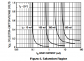
The minimum base current to have 1V drop is less than 1 mA implies nominal hFE =130 at Vce=1 just out of saturation dissipating 130 mW.

If there is any reason to be miserly about drive current you can pick any value between 1 and 13 mA, but most likely with Ib=13 it will saturate at Vce(sat) = 50 mV @ 25'C and 11.95 across coil. and higher Vce at -40'C

I generally chose Ic/Ib=20 for small relays.

It doesn't matter that much on 12V but more so if the relay coil was 3V.

1706942123665.png
 

Attachments

Sensacell

Joined Jun 19, 2012
3,786
This is a very interesting thread to me - it illuminates the dark corners or electronic design where numeric calculations fail, and this is a scary idea for beginners who are taught that math has all the answers.
If I was a beginner, this thread would surely leave me terribly confused.

So how to help people grapple with this?

Maybe by taking a more conceptual approach to the problem?
Think of domains of operation? Linear Mode, Saturation Mode, what do these mean? what happens when these modes overlap, and how does the "bad" hFE parameter affect where these cross-over points occur?

Food for thought.
 
Last edited:

Thread Starter

PorkChopJohn

Joined Feb 1, 2024
17
Ok it is very confusing to me atm but one day I will understand it better.

Thank you again for all your help!
 
Last edited:

MrChips

Joined Oct 2, 2009
34,889
Engineering design is about tolerances.
Know what the minimum and maximum values are for any particular parameter.
Know that sometimes components might be substituted for whatever reasons.
With these in mind, there is always a range of values that will work for a specific application and for otherwise non-specific application.
And finally, proper engineer design dictates that there must be a margin of error included in the design.
 

tonyStewart

Joined May 8, 2012
238
Transistors are inherently non-linear with quadratic Vbe controlled collector current. When used in an "H-bias" with linear emitter resistor the base impedance becomes more linear (hFE*Re) . But we don't want to add resistance to the inherently non-linear switch.

So we learn to understand the datasheet plots and I think of the transition from a "linear" to a binary switch requires reducing hFE by a factor of 10 for a design target using the max hFE.

Others are happy just to use Ic/Ib=10 or 20 or 50 for superbeta and ultrabeta types.
 

dl324

Joined Mar 30, 2015
18,381
I did saturation tests on 6 different transistors I had handy. I picked 2 of each randomly. I had hundreds of each transistor to choose from. The BC547 were next to each other on tape.

I am not suggesting in any way that the OP should disregard the datasheet beta that guarantees saturation. This is just to illustrate that higher values will still allow the transistor to enter saturation mode.

BC337 results for the OP:
1707001490058.png
1707001513644.png
1707001741674.png
All 6 transistor types exhibited saturation at a beta of 60, or higher. Which is what I stated my experience was earlier with 2N3904 and a house marked NPN.
 

Attachments

Last edited:

Thread Starter

PorkChopJohn

Joined Feb 1, 2024
17
Appreciate all your efforts to put into my question. I’ve been reading them every day and each time helped me understand a little more so I’m not completely lost. Although I still have confusion in my head I think it’s normal for beginners. It will just take some time for me to get there.
 

MrChips

Joined Oct 2, 2009
34,889
@dl324 Before you posted your research, I was going to suggest the following.

This calls for an experiment. You can determine your own limits and hFE values by conducting an exhaustive survey of all possible transistors under all possible conditions.

1) Take 100 BC337 transistors from the same manufacturing batch and measure hFE over a range of collector currents.
2) Repeat with 100 BC337 from different manufacturing batches.
3) Repeat the above with different types of transistors, ranging from small signal to power transistors
4) Repeat the above over different operating supply voltages.
5) Repeat the above over a range of ambient temperatures.

Okay. One does not have the time to conduct such an exhaustive test. Hence let us focus on one series of test for a single BC337 transistor in a specific application, i.e. driving a specific relay at a specific current and voltage at a specific temperature.
What is the range of values of base resistor (i.e. base current) over which the relay is activated?

For your answer, see post #46.
 

LvW

Joined Jun 13, 2013
2,031
Now can I say we want the transistor stays in saturation mode? And when the saturation mode it doesn’t matter if the base current (or V_be) a bit higher or lower, it will not affect the collector current (or V_ce)?
I really don't want to confuse you any more, but the following is important for understanding the role of the base current in the "saturation" case:

* It is not the base current Ib that causes the transistor to saturate (collector current Ic is controlled/determined by the voltage Vbe) - this base current is only an indication that the transistor is operating in saturation mode.

* Saturation is defined as the state in which the base-collector junction operates in the forward direction - i.e. Vc<Vb .
Therefore, the base-emitter voltage Vbe must be large enough to cause a voltage drop Ic*Rc across the collector resistor which makes Vbc>0 (in contrast to the "normal" mode for amplification purposes).

* This means that the base-collector diode is forward biased and a relatively large current flows from the base to the collector (npn case) - in addition to the "normal" base current to the emitter.
This is the actual reason for calculating with a drastically reduced factor B=Ic/Ib.
(Let me add that, for my opinion, the name "current gain" for the factor B is somewhat misleading).

* In other words, the series resistor at the base must be selected so that it allows a base-emitter voltage Vbe of about 0.7V at the (increased) base current associated with the saturation state.

* And that is why the actual B value is not particularly important when calculating the resistances at the base - the B value just has to be small enough to be sure that the B-C junction works in the forward direction.
 
Last edited:

Thread Starter

PorkChopJohn

Joined Feb 1, 2024
17
I really don't want to confuse you any more, but the following is important for understanding the role of the base current in the "saturation" case:

* It is not the base current Ib that causes the transistor to saturate (collector current Ic is controlled/determined by the voltage Vbe) - this base current is only an indication that the transistor is operating in saturation mode.

* Saturation is defined as the state in which the base-collector junction operates in the forward direction - i.e. Vc<Vb .
Therefore, the base-emitter voltage Vbe must be large enough to cause a voltage drop Ic*Rc across the collector resistor which makes Vbc>0 (in contrast to the "normal" mode for amplification purposes).

* This means that the base-collector diode is forward biased and a relatively large current flows from the base to the collector (npn case) - in addition to the "normal" base current to the emitter.
This is the actual reason for calculating with a drastically reduced factor B=Ic/Ib.
(Let me add that, for my opinion, the name "current gain" for the factor B is somewhat misleading).

* In other words, the series resistor at the base must be selected so that it allows a base-emitter voltage Vbe of about 0.7V at the (increased) base current associated with the saturation state.

* And that is why the actual B value is not particularly important when calculating the resistances at the base - the B value just has to be small enough to be sure that the B-C junction works in the forward direction.
I will not be more confused haha. Thank you!!
 

MrChips

Joined Oct 2, 2009
34,889
Hi all, I've been asked to calculate base current from a provided collector current which is 141mA.
BC337 is the transistor we are using in this question.
I've searched online for hFE, but got a bit confused as it has several hFE number.

my question is why there are so many hFE and what's the difference between them? How do I know which hFE should I choose.
Thank you very much for your help.
That was your opening post.

Yes it is being used as a switch. Here is the diagram
View attachment 314146
Initially we’ve been asked to find a current value from given R_coil=85Ω and V_coil=12V from relay. I got the current flow through relay and collector which is 12V/85Ω=141mA (I might be wrong though). Then we need to choose a transistor from bunch of they provided ones (I chose BC337 as 141mA in the range) asked to find base current from previous calculations. That’s where I got stuck as I don’t know which hFE to use to get the base current. There are following questions that I need to use this base current value to do further calculations. So I kinda need a specific base value.
From your opening post, hFE = 100 is adequate.
From the actual circuit application hFE = 10 is the rule.

Can you see now why you need to state the full problem?
 

dl324

Joined Mar 30, 2015
18,381
I will not be more confused haha. Thank you!!
The beta of 10 specified in the datasheet is a value that guarantees the transistor will saturate under all conditions.

The two BC337 datasheets I have (On Semi and Fairchild) don't give the effect of temperature on beta. A Siemens BCX59 datasheet does:
1707148324948.png
You can see from this curve tracer display that current and Vce also affect current gain:
curveTracerNPN.jpg
Vertical axis = collector current, horizontal = collector emitter voltage. Transistor is not BC337.
 

LvW

Joined Jun 13, 2013
2,031
The beta of 10 specified in the datasheet is a value that guarantees the transistor will saturate under all conditions.
Question: For saturation, do they (in the data sheet) really specify "beta" or "B" ?
My question is because "beta=hfe" is a small-signal parameter which must not be used Instead of "B" for a ratio of two DC currents (B=Ic/Ib).
 

dl324

Joined Mar 30, 2015
18,381
For saturation, do they (in the data sheet) really specify "beta" or "B" ?
From what I've seen, they just give a base and collector calculation and leave the arithmetic to the user.

I treat \( current\ gain,\ beta,\ β,\ hFE,\ h_{fe},\ h_{FE} \) as all referring to current gain. Technically, hfe and hFE aren't the correct spelling, but we can understand the intended meaning.
 

WBahn

Joined Mar 31, 2012
32,935
Question: For saturation, do they (in the data sheet) really specify "beta" or "B" ?
My question is because "beta=hfe" is a small-signal parameter which must not be used Instead of "B" for a ratio of two DC currents (B=Ic/Ib).
Most data sheets specify saturation test conditions either with explicit values for Ic, Ib, Vce, and Tj, or they specify the ratio as Ic/Ib. They don't generally use either hfe or hFE.

In conversational and most informal use, ß (lower case beta) is used for all of the above with the distinction being established by context of use. May not be ideal, but it is what it is. Upper case beta is very seldom seen except in the most formal of context because of the difficulty of distinguishing between an upper case beta and an upper case B. Instead, what you commonly see is a lower-case beta with a subcripted upper-case F, ß_F, to indicate the DC current gain.
 

LvW

Joined Jun 13, 2013
2,031
Upper case beta is very seldom seen except in the most formal of context because of the difficulty of distinguishing between an upper case beta and an upper case B. Instead, what you commonly see is a lower-case beta with a subcripted upper-case F, ß_F, to indicate the DC current gain.
Well, there is probably a difference in the syntax of this quantity:
* USA: h_fe (or β) and h_FE
* Germany: h21 (or β) and B

However, the most important thing is that there are no misconceptions about the meaning of the symbols.
 
Last edited:

Thread Starter

PorkChopJohn

Joined Feb 1, 2024
17
That was your opening post.


From your opening post, hFE = 100 is adequate.
From the actual circuit application hFE = 10 is the rule.

Can you see now why you need to state the full problem?
Yes. I didn’t understand the linear and saturated stage that’s why I got confused about hFE
 
Top