TL431 + LM317 + PNP = reg confusion

Jony130

Joined Feb 17, 2009
5,600
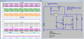
Remove Q1 and increase R5 to 500R. And you will see that this circuit will oscillate without Q1 (enable .tran 50m startup ).
 

Papabravo

Joined Feb 24, 2006
22,111
Remove Q1 and increase R5 to 500R. And you will see that this circuit will oscillate without Q1 (enable .tran 50m startup ).
Right. That is the insufficient load current scenario. Interesting and true, but not necessarily part of this particular thread IMHO. The TS was interested in understanding how the circuit, that was represented by a product that he had already purchased, was actually working. Multiple simulations without models that duplicated his exact situation were attempted with limited success. It took some digging to uncover what might actually be going on. All in all, for this application, I would be looking for an alternate solution with particular specifications for current voltage and voltage ripple.
 
Last edited:

Papabravo

Joined Feb 24, 2006
22,111
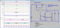
But we can make the circuit stable just by moving the bottom leg of a C3 to Vref.
I'll give that a try and get back to you.
1655233650645.png
OK. That also works and changes the nature of things. I still think the ripple is too much for an allegedly stable linear regulator.
I do like this one a bit better, thanks for the suggestion. Q1 is now on all the time with R4=0.47Ω
1655233927687.png
 
Last edited:

Papabravo

Joined Feb 24, 2006
22,111
Thank you to @Jony130 for another helpful suggestion. This might confirm that the product purchased by the TS might suffer from one or more design flaws if he can observe and measure noticeable amounts of voltage and or current ripple on the output. We can only wonder if his circuit and any of the simulations we have tried are related in a meaningful way.

As a first step, I'd like to ask if anybody has a line on a model for:
  1. NJW0302G PNP Transistor
  2. TL431AC, if anybody thinks this might be relevant
 

Jony130

Joined Feb 17, 2009
5,600
I still think the ripple is too much for an allegedly stable linear regulator.
Add some ESR, 0.1Ω or less to the output cap.

This might confirm that the product purchased by the TS might suffer from one or more design flaws if he can observe and measure noticeable amounts of voltage and or current ripple on the output.
Yes, it is still a very bad design. I don't like it at all.

We can only wonder if his circuit and any of the simulations we have tried are related in a meaningful way.
If I find some time I will try to check it the day after tomorrow on the breadboard.
 

Jony130

Joined Feb 17, 2009
5,600
NJW0302G PNP Transistor
.MODEL NJW0302G pnp
+IS=5.16751e-16 BF=114.657 NF=0.895716 VAF=50.2189
+IKF=6.409 ISE=3.9641e-15 NE=4 BR=1.47167
+NR=0.923324 VAR=255.567 IKR=6.34299 ISC=3.96408e-15
+NC=2.82194 RB=2.66347 IRB=0.1 RBM=2.0828
+RE=0.0001 RC=0.0652395 XTB=1.45322 XTI=1.08126
+EG=1.05 CJE=2.14504e-09 VJE=0.4 MJE=0.376227
+TF=2.16864e-09 XTF=1000 VTF=843.737 ITF=501.348
+CJC=5e-10 VJC=0.95 MJC=0.251547 XCJC=1
+FC=0.8 CJS=0 VJS=0.75 MJS=0.5
+TR=1e-07 PTF=0 KF=0 AF=1

TL431AC, if anybody thinks this might be relevant
But you already have the TL431 model.
 

BobTPH

Joined Jun 5, 2013
11,654
Has anyone figured out what the purpose of the TL431 is in this circuit? You can certainly leave it out and adjust the other resistors to get a working regulator with pass transistor, no?

Bob
 

ronsimpson

Joined Oct 7, 2019
4,814
The LM317 has gain. The TL431 has gain. There is/was no compensation with the TL431. The high frequency gain is too high.
My first thought was why is this not oscillating. There are so many things that effect the oscillation that it can be hard to find.

The TL431 is a very good error amp/reference. I question if it is worth adding it. There is much work in making the TL431 work right.
 

Papabravo

Joined Feb 24, 2006
22,111
@ericgibbs, @BobTPH & @ronsimpson,

I was certainly puzzled by this circuit but approached it with an open mind and some level of curiosity. After playing with the simulations and trying various parts and models I have come to the conclusion that it is a design with a sensitive dependence on device properties and may not actually works as presented by the TS. That there is a combination of real parts that allows the circuit to sort of work is plausible, but I have come to the conclusion that there is nothing to learn here and that it deserves to be consigned to the dustbin of history. I certainly don't plan to spend additional time on it.
 

Jony130

Joined Feb 17, 2009
5,600
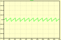
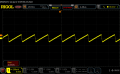
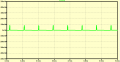
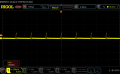
Sim VS Reality in AC coupling mode Vout = 5V and IL = 25mA

Without Cout capacitor

Sim:
untitled.PNG

Real circuit:

RigolDS2.png


With the Cout = 680μF

Sim:
untitled2.PNG

Real circuit:

RigolDS1.png
 
I came across this thread while searching for the parts combination I saw in another one of these power supplies, which unfortunately you don't find until after you've already got it and can read off the part numbers. I was a bit nervous when I read through the discussion, but then from a quick scope reading earlier today didn't see any of the sawtooth noise reported earlier, just maybe 5mV of random noise of undetermined frequency which was most likely caused by the quick-and-dirty test lead hookup I used. Could they have revised the design in the meantime, or did the OP get a bad clone of the original, which seems to be from Weilang Audio/BRZHifi?
 
No, just the black box like everyone else, but there are quite different components used, for example the main filter caps are (presumably) fake Nichicon PM's rather than (fake?) Elna RE3's, and the EMI filter caps are some sort of X2's (hard to read) rather than RIFA PHE's.
 
A note to the above, there are multiple different circuit diagrams for these supplies around, e.g this and this which means either there were errors made in reverse-engineering the circuit or there were errors made in copying the original circuit by the cloners. The latter would explain some of the odd performance and otherwise unexplainable circuit "features", there was an original that made sense and then it was copied with errors by cloners.
 
Top