Timers start signal.

Thread Starter

Xavier Pacheco Paulino

Joined Oct 21, 2015
728
Hi,

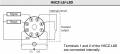
I attach two pictures of two different timers that I have. I really do not understand very well the way of starting timing. Are they the same? On Timer1 you can see the signal must be in PIN4. But what kind of signal? However, on Timer2 it says 1&2 trigger signal or Pulse Dry Contact. What does this mean?
 

Attachments

Last edited:

Reloadron

Joined Jan 15, 2015
7,888
On your first image the Timer On is pin 4 to pin 1 (0 Volt) which is common. Take a look at the data sheet. Scroll down below the image you posted on page 6 Terminal Arrangement. They give an example of the Input Circuit using +14 Volts applied with a 1 K Ohm pull up resistor. Then they show using a dry contact switch and a few open collector transistor circuits to run a count. The whole idea is pin 4 is taken to a logic low. You can do this with a transistor external circuit or a dry contact switch.

Your second image is about the same thing Dry Contact. Again dry contact just means an external contact closure between the two terminals 1 & 2.

Ron
 

Thread Starter

Xavier Pacheco Paulino

Joined Oct 21, 2015
728
On your first image the Timer On is pin 4 to pin 1 (0 Volt) which is common. Take a look at the data sheet. Scroll down below the image you posted on page 6 Terminal Arrangement. They give an example of the Input Circuit using +14 Volts applied with a 1 K Ohm pull up resistor. Then they show using a dry contact switch and a few open collector transistor circuits to run a count. The whole idea is pin 4 is taken to a logic low. You can do this with a transistor external circuit or a dry contact switch.

Your second image is about the same thing Dry Contact. Again dry contact just means an external contact closure between the two terminals 1 & 2.

Ron
Perfect. Thank you.
 
Top