Facebook
 Google
 GitHub
 Linkedin
Hello Everyone,
I wanted to start by saying I'm new here and somewhat new to electronics in general. I'm kind of self educating at the moment and I'm working on transistors. I had a little project in mind to use one and help me learn but I'm having no luck. I'm wondering if i'm not using the wrong type of transistor.
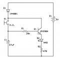
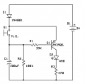
I believe I have replicated the attached circuit but I don't see a delay. The LED just turns on right away.
The values of my resistors and cap are a bit different but i dont think they should impact it this way.
1K resistor to LED (same as drawing)
270k resistor to base of transistor (instead of 33k)
Additional 10k resistor from+ side to the capacitor. Right about where the push button is in the drawing.
Capacitor is only 470uF(instead of 1000uF) *this was the reason for the 10k to slow the charge down some
Some of the transistors I've tried are
TIP3055
PN2222
PN4393
I've attached the schematic as well as a picture of it on my breadboard. Any advice is greatly appreciated.


I wanted to start by saying I'm new here and somewhat new to electronics in general. I'm kind of self educating at the moment and I'm working on transistors. I had a little project in mind to use one and help me learn but I'm having no luck. I'm wondering if i'm not using the wrong type of transistor.
I believe I have replicated the attached circuit but I don't see a delay. The LED just turns on right away.
The values of my resistors and cap are a bit different but i dont think they should impact it this way.
1K resistor to LED (same as drawing)
270k resistor to base of transistor (instead of 33k)
Additional 10k resistor from+ side to the capacitor. Right about where the push button is in the drawing.
Capacitor is only 470uF(instead of 1000uF) *this was the reason for the 10k to slow the charge down some
Some of the transistors I've tried are
TIP3055
PN2222
PN4393
I've attached the schematic as well as a picture of it on my breadboard. Any advice is greatly appreciated.