Facebook
 Google
 GitHub
 Linkedin
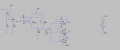
There is a pulse shown in the picture.The pulse voltage are -2V to -5V and the width is 200ns.
Is there a component which could take this pulse and relpicate it three times?
Three outputs which are equal to the pulse i entered.
Thanks.

Is there a component which could take this pulse and relpicate it three times?
Three outputs which are equal to the pulse i entered.
Thanks.
Last edited: