Three Voltmeter Method Analysis

Thread Starter

MrAl

Joined Jun 17, 2014
13,851
Hello there,

I am looking into finding out the error in measurement of this method for measuring phase angle in a circuit. The example circuit is a simple series RC circuit. R2=10, C=1000uf, f=50Hz.
The three voltage measurements are Vs, Vr, and Vz.
Vs is the known source AC voltage used to drive the network.
Vz is the measured AC voltage across the R2 and C network.
Vr is the measured AC voltage across an additional resistor R1 placed in series with the series R2 and C string.
R1 is an extra resistor used to make this measurement.
The formula is (current phase angle or R2 and C in degrees):
TH=(180*acos((-Vz^2+Vs^2-Vr^2)/(2*Vr*Vz)))/pi
So there we see the three measured voltages and a little math and the result is the phase angle TH.
Since all three are measured, that means their variables represent the magnitudes of all three voltages.
Vs, for now, is assumed to be known but not directly measured. Later I will consider the measurement effects for that also.

Since we have to choose R1, the question arises about what value to use. It seems that when R1 is comparable to R2 the measurement is more accurate, but the meter accuracy is very important as even a 2 percent error can result in a very big error in the phase angle calculated with the given formula, which is the Three Voltmeter Method.

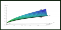
Here is a little graph that shows the results and the errors. Az is the percent error in both Vz and Vr, assumed to be measured with the same or similar meter. R1 is varied from 1 to 10 Ohms, Az is varied from 0.01 to 0.1 which is 1 percent to 10 percent error in the meters.

Anybody want to verify this or just look into it a little? It is very possible that measurement of Vs will help with the accuracy however the difference of squares could still be a source of error.
 

Attachments

Thread Starter

MrAl

Joined Jun 17, 2014
13,851
Hello there,

I am looking into finding out the error in measurement of this method for measuring phase angle in a circuit. The example circuit is a simple series RC circuit. R2=10, C=1000uf, f=50Hz.
The three voltage measurements are Vs, Vr, and Vz.
Vs is the known source AC voltage used to drive the network.
Vz is the measured AC voltage across the R2 and C network.
Vr is the measured AC voltage across an additional resistor R1 placed in series with the series R2 and C string.
R1 is an extra resistor used to make this measurement.
The formula is (current phase angle or R2 and C in degrees):
TH=(180*acos((-Vz^2+Vs^2-Vr^2)/(2*Vr*Vz)))/pi
So there we see the three measured voltages and a little math and the result is the phase angle TH.
Since all three are measured, that means their variables represent the magnitudes of all three voltages.
Vs, for now, is assumed to be known but not directly measured. Later I will consider the measurement effects for that also.

Since we have to choose R1, the question arises about what value to use. It seems that when R1 is comparable to R2 the measurement is more accurate, but the meter accuracy is very important as even a 2 percent error can result in a very big error in the phase angle calculated with the given formula, which is the Three Voltmeter Method.

Here is a little graph that shows the results and the errors. Az is the percent error in both Vz and Vr, assumed to be measured with the same or similar meter. R1 is varied from 1 to 10 Ohms, Az is varied from 0.01 to 0.1 which is 1 percent to 10 percent error in the meters.

Anybody want to verify this or just look into it a little? It is very possible that measurement of Vs will help with the accuracy however the difference of squares could still be a source of error.
Hello again,

I looked at this a little more and found that the error in the measured value of Vs can cancel the errors in Vr and Vz if the same meter is used, but only to a point. The thing is, the voltages can be all different so we then start dealing with the linearity of the meters as well as some other real world considerations. In pure theory though, the error is Vs cancels the errors in Vr and Vz completely if they are all the same exact percentage. In the real world linearity will change that though so we have to be careful.
 
You are correct about linearity changing across the ranges. But if you have a reputable meter, that linearity will be specified. Depending on the accuracy level you are looking at, perhaps that error may be neglected.
 

Thread Starter

MrAl

Joined Jun 17, 2014
13,851
if i read it correctly, circuit is something like this? so Vs=Vr+Vz?
View attachment 372707
Hi,

Oh that's a nice drawing, thanks for that.

But going by the drawing you show Vr and Vz as being measured by regular meters. That would mean what you really seem to be adding is:
|Vs|=|Vr|+|Vz|

and that is generally not true as I think you know now, and was also indicated by WBahn.

Here are the two voltages in full form:
Vzjw=(Vs*(j*w*C*R2+1))/(j*w*C*R2+j*w*C*R1+1)
Vrjw=(j*Vs*w*C*R1)/(j*w*C*R2+j*w*C*R1+1)

Now it is true that:
Vs=Vzjw+Vrjw

but if we take the norm of the two first we get (the 'a' in Vza and Vra just indicates it's the amplitude):
Vza=(Vs*sqrt(w^2*C^2*R2^2+1))/sqrt((w*C*R2+w*C*R1)^2+1)
Vra=(Vs*w*C*R1)/sqrt((w*C*R2+w*C*R1)^2+1)

and now if we add:
V=Vza+Vra

we get:
V=(Vs*(sqrt(w^2*C^2*R2^2+1)+w*C*R1))/sqrt(w^2*C^2*R2^2+2*w^2*C^2*R1*R2+w^2*C^2*R1^2+1)

which certainly is not Vs, and substituting the values R2=10, C=1000uf, w=2*pi*50, R1=10.49438508747577, Vs=100 we get:
V=101.1989601212998

and of course 101.2vac is not equal to 100vac. (Note that R1 value was chosen to force |Vr|=|Vz| for other reasons).

Furthermore, if we start with the formula for the phase angle and substitute Vs=Vz+Vr (where Vz is Vza and Vr=Vra) we get:
TH=0

If instead we substitute Vr=Vrjw and Vz=Vzjw we end up with:
TH=180/pi*acos(1)
which of course comes out again to:
TH=0

Since we know the value of R1 with a simple measurement, this seems to work also (but here |Vz|=|Vr| is first forced by adjusting R1):
R2=(Vs^2*R1)/(2*Vz^2)-R1
C=(2*Vz^2)/(Vs*sqrt(4*Vz^2-Vs^2)*w*R1)

That seems to work, but the requirement is we have to get Vr to equal Vz to use it. It is only for an RC network so we'd have to develop something for RL also, and see if we can find something like that for an RLC network.

The thing I liked about this method was that we don't need a phase meter or scope to measure the phase, at least in the theory anyway. In practice we have to watch for errors, but it could still work out unless maybe the voltage measurements are at very very different levels.
 
Last edited:

panic mode

Joined Oct 10, 2011
5,399
no problem, i am visual person so having that helps. i am low of caffeine but lets see

Zall = sqrt( (R1+R2)^2 + 1/(w*C)^2) = sqrt( (w*C)^2*(R1+R2)^2 + 1)/(w*C) = sqrt((w*C*R1+w*C*R2)^2+1)/(w*C)
Z2= sqrt( R2^2 + 1/(w*C)^2)=sqrt((w*C*R2)^1+1)/(w*C)

I = Vs/Zall = Vs*(w*C)/sqrt((w*C*R1+w*C*R2)^2+1)

Vra=I*R1=R1*(Vs*w*C)/sqrt((w*C*R1+w*C*R2)^2+1)
Vza=I*Z2=Vs*sqrt((w*C*R2)^2+1)/sqrt((w*C*R1+w*C*R2)^2+1)

this matches your result for amplitude so without diving deeper, it looks like at least that part of your math checks out...
 

kiroma

Joined Apr 30, 2014
292
You guys were low on likes (but a bit higher in caffeine), so I gave it a bump.
If I had time to analyze all you guys wrote, I'd enjoy it with a big cup of coffee.
I endorse who has time, will, and knowledge to keep up with good theory.
 

Thread Starter

MrAl

Joined Jun 17, 2014
13,851
no problem, i am visual person so having that helps. i am low of caffeine but lets see

Zall = sqrt( (R1+R2)^2 + 1/(w*C)^2) = sqrt( (w*C)^2*(R1+R2)^2 + 1)/(w*C) = sqrt((w*C*R1+w*C*R2)^2+1)/(w*C)
Z2= sqrt( R2^2 + 1/(w*C)^2)=sqrt((w*C*R2)^1+1)/(w*C)

I = Vs/Zall = Vs*(w*C)/sqrt((w*C*R1+w*C*R2)^2+1)

Vra=I*R1=R1*(Vs*w*C)/sqrt((w*C*R1+w*C*R2)^2+1)
Vza=I*Z2=Vs*sqrt((w*C*R2)^2+1)/sqrt((w*C*R1+w*C*R2)^2+1)

this matches your result for amplitude so without diving deeper, it looks like at least that part of your math checks out...
Hi,

I used math software for my previous reply so the math should be right, it's the application of the math that has to be done according to electric circuit theory. Since the circuit is so simple, it should be right, but you can test it in a simulator too that's usually interesting. With a lot of these calculations, you can get 6 digits to match the math sometimes even better, but we usually don't need that many.
I can plug the circuit into my personal simulator and see what formulas that comes up with. Not sure why I did not do that yet, maybe it seemed too simple. After all, it's just two resistors in series with a capacitor (ha ha) for this one test circuit.
 
Top