Three-phase circuits problems

Thread Starter

PsySc0rpi0n

Joined Mar 4, 2014
1,786
My exam was today and I think it didn't go very well for me but I'm going to pray to have enough points to complete this class.

The 3-phased problem was:

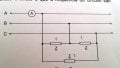
Consider the attached circuit.
The resistor Power is 200W. The current at line A is 15A. The circuit is "balanced" and at a direct phase sequence. The frequency is 50Hz.

a) Calculate the 3 voltages at the neutral-phase at module and phase (_I don't know how to translate the text accurately, but I think we were asked to find the Line and Phase voltages).

b) Calculate the Power Factor of the load connected at a Delta setup.

c) Calculate the value of the components connected at a "Y" setup that makes the global Power Factor to be unitary.


I'll post my calcs later!
 

Attachments

t_n_k

Joined Mar 6, 2009
5,455
Perhaps something was lost in translation.

Is the total three phase resistive power 200W or is it 200W per phase?

The implication in the question that the power factor is other than unity means that there will be reactive components in the load as well. With the information given thus far it is impossible to resolve the question. Were you given an apparent power value as well?
 

Thread Starter

PsySc0rpi0n

Joined Mar 4, 2014
1,786
Perhaps something was lost in translation.

Is the total three phase resistive power 200W or is it 200W per phase?

The implication in the question that the power factor is other than unity means that there will be reactive components in the load as well. With the information given thus far it is impossible to resolve the question. Were you given an apparent power value as well?
200W is the resistor power. Not the phase power or the 3 phase power...
It's the power only for the resistor...

As they gave the current in each line, I know that the phase current is Line current/sqrt 3 because it's a balanced Delta setup!.

With that phase current i can calculate resistor value with P=R*I²<=> 200=R.(Iline/sqrt 3)².

After I have phase impedance I can calculate phase voltage which will be the same as Line Voltage as we are with a Delta setup...

I think this was what teacher asked! But I don't know if my thoughts are correct!
 

t_n_k

Joined Mar 6, 2009
5,455
200W is the resistor power. Not the phase power or the 3 phase power...
It's the power only for the resistor...

As they gave the current in each line, I know that the phase current is Line current/sqrt 3 because it's a balanced Delta setup!.

With that phase current i can calculate resistor value with P=R*I²<=> 200=R.(Iline/sqrt 3)².

After I have phase impedance I can calculate phase voltage which will be the same as Line Voltage as we are with a Delta setup...

I think this was what teacher asked! But I don't know if my thoughts are correct!
This is where I suspect communication goes astray with meaning in particular languages and the translation involved.

If you say 200W is the resistor power it can also be interpreted as meaning the resistor power rating which would be even more confusing in the context of the question as you state it in post #41.

I might then ask where is the 200W power being dissipated? I assume this is heat dissipation in the the resistive component of the load impedances. Is this 200W spread across the three phases or is it the power being dissipated in each individual load?

One must also be careful about differentiating real and apparent power. I make this point because it seems from the question as stated in post #41 that the load impedance is complex rather than simply resistive. I assume that to be the case since the part (c) of the question asks what Y connected impedance can return the system power factor to unity. If the loads were purely resistive then the corresponding system power fatcor would already be unity and no additional impedance [reactance] would be required to set unity power factor.
 

Thread Starter

PsySc0rpi0n

Joined Mar 4, 2014
1,786
The Resistor Power is the Resistor Power. I can' say it in any other words. There is a resistor in each phase that dissipates 200W of heat!

And yes, there is an inductor in series with that resistor. I thought that was clear in the first place by the .asc file I uploaded in post #41. Each "Z" letter in each phase means a resistor and an inductor in series.

Sorry for the mess!
 

t_n_k

Joined Mar 6, 2009
5,455
No problem - one needs to be very clear about what is stated. Rather than posting an asc file it's probably better to post a screen shot of the schematic. That way even people who don't use LTspice can understand the problem. I didn't bother opening the file.
 

Thread Starter

PsySc0rpi0n

Joined Mar 4, 2014
1,786
No problem - one needs to be very clear about what is stated. Rather than posting an asc file it's probably better to post a screen shot of the schematic. That way even people who don't use LTspice can understand the problem. I didn't bother opening the file.

I have uploaded a print screen of the circuit at post #41!
 

t_n_k

Joined Mar 6, 2009
5,455
OK I had a look. All is now much clearer.

I would proceed with the solution as follows:

  1. The first step is as you suggest:

    \(\text{R=\frac{200 \times \ 3}{225}=2.667 \ ohms}\)

  2. The per phase delta impedance is therefore:

    \(\text{Z_d=2.667 +j\omega \times \ \frac{1}{1000} = 2.667 +j0.3142 \ ohms}\)

  3. The equivalent star impedance is therefore:

    \(\text{Z_s=\frac{Z_d}{3}=0.889+j0.1047 \ ohms}\)

  4. The corresponding line-to-neutral voltage magnitude is therefore:

    \(\text{|V|=15\times |Z_s| = 15\times 0.895 =13.425 \ volts}\)

  5. The line current lags the line-to-neutral voltage by:

    \(\text{Arg(Z_s)=6.718^o}\)

  6. If the A phase line-to-neutral voltage has reference 0° phase, then the A phase current would be

    \(\text{I_A=15\underline{|-6.718^o} = 14.897-j1.755 \ amps}\)

  7. The load power factor would be:

    \(\text{p.f=\cos \(6.718^o\)=0.993 \ [lagging]}\)

  8. To adjust the system pf to unity requires a 90° leading current draw of 1.755 amps using a capacitance.

  9. The required per-phase capacitance in star configuration would be:

    \(\text{C=\frac{1.755}{\omega \times |V_{line-to-neutral}|}=\frac{1.755}{314.16 \times 13.425}=416.11 \ uF}\)
 
Last edited:
Top