Three Little Switches...

Thread Starter

luvv

Joined May 26, 2011
191
Hello,

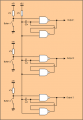
Here is what i am wanting to achieve..

Three momentary n/o switches only one can be on at anytime..

Pushing any one of the three buttons latches the one on and disables the other two.

These will be used as "enable" switches so break before make function isn't all that important.

I know the description is a little vague but i'm sure you get the idea.

Thanks

-luvv-
 

DickCappels

Joined Aug 21, 2008
10,153
That's a popular logic design question. Have a look at these two circuits at the URL below. I think its the second one that you are looking for -you can replace the photo transistors with momentary switches.

http://www.bowdenshobbycircuits.info/page7.htm
A little past halfway down the page is Game Show Indicator Lights (Who's First)
Below that is Pinewood Derby Finish Line Lamps
 

JDT

Joined Feb 12, 2009
657
These are called "radio buttons". Used to be mechanical.

Here is a simple circuit using CMOS NAND gates that should work. Not tested. Can be extended to any number.

Each button uses a 2 gates cross-coupled as a "latch". When a latch flips, it creates a negative spike through the capacitor to reset the others. As the button is pressed for longer than the length of the spike, one stays on.
 

Attachments

Thread Starter

luvv

Joined May 26, 2011
191
Thanks guys,

That was just what i was looking for, i had played w/ flip flop circuits but had no idea how to chain them beyond two.

It makes sense now, all i have in the way of nand gates is a cd4093(s) would this be appropriate?

Thanks again,

-luvv-
 

DickCappels

Joined Aug 21, 2008
10,153
Not sure if this is important or not, but with the circuit JDT posted, the output will indicate the last button pressed instead of the first button pressed.
 

crutschow

Joined Mar 14, 2008
34,281
Not sure if this is important or not, but with the circuit JDT posted, the output will indicate the last button pressed instead of the first button pressed.
I see your point. Does the OP want Radio Buttons, where it's always the last button pressed that is active, or Quiz Show buttons, where the first button pressed locks out all the others until the system is reset.
 

Thread Starter

luvv

Joined May 26, 2011
191
Yes i think that is exactly what i want,last button pushed is the active one.

Do you think the 4093 ic will suffice ?

Thanks

-luvv-
 

JDT

Joined Feb 12, 2009
657
I have revised my circuit now, to get rid of the capacitors. Proper logic design does not rely on spikes from capacitors. Output is last button pushed of course.

I would recommend using the CMOS ic's indicated. You can use a 4093 for instead of the 4011. Probably better, in fact.

May come up a a random state at power-up. Might be all outputs off. With a little more circuitry you could make it come up at a known state at power up.

If you wanted minimum component count and size I would use an 8-pin PIC with its internal pull-ups but that's another story! (8 pins = 3 inputs, 3 outputs + power)
 

Attachments

Thread Starter

luvv

Joined May 26, 2011
191
Thanks JDT

Seriously awesome of you to take the time to work up a schematic and even more cool of you to revise it for reliability.

I've ordered 4001(s) & 4011(s) after i get them ill give it go and update the thread w/ a vid so you can see the fruits of your labor.

Thanks again
-luvv-
 

Thread Starter

luvv

Joined May 26, 2011
191
Ok, so i tried to translate the drawing you did to pins on the chips...

Think Ive done something horribly wrong, here is the schematic i came up w/..

Not sure where I went wrong but it don't function on bread board so i assume it's my schematic.

Could someone straighten it out for me?

Thanks,

-luvv-
 

Attachments

JDT

Joined Feb 12, 2009
657
Looks all right. In what way does it not work? What voltage/logic levels do you get when you first power it up? What happens when you press a button? Anything change?

This being a logic circuit, one quick test with a DVM is to measure the voltage levels on the pins. Should be 0V or supply volts, anything else could be trouble.
 

Thread Starter

luvv

Joined May 26, 2011
191
All 3 outs are high at power on, pushing sw1 or 2 turns off output one and two :confused:
Pushing sw3 turns off out 3 but don't effect out one or 2...

I would say my wiring was bass akwards but Ive been over and over it and can't find a issue one.

Perhaps it's a bad chip or breadboard issues..i don't know, but i give up im just just gonna buy a 3 position mechanical and call it a day.

Thanks for all the input though, guess the simplest solution is sometimes the best.

-luvv-
 

Thread Starter

luvv

Joined May 26, 2011
191
Are you sure U1 and U2 are CD4011 and U3 is a CD 4001?
Yea well as certain as markings on the chips they are CD4011BE and CD4001BE from Ti.

The problem is most likely between the bread board and the chair as i found the schematic not exactly breadboard friendly.

There is also a slight chance the chips are damaged as the company don't properly package them tho i have never had a issue in two years of buying from them.

Another thing i didn't do was tie the unused gates high or low which as i understand it is good practice.

Bugs me knowing something should work and don't so i guess ill take another run at it.

I'll give the thing a entire bread board all to itself and make solid wire jumpers so there for sure isn't a connection issue.

If it it's still screwy ill up a vid so you guys can look over my wiring and find my issue.

Thanks,
-luvv-
 

Thread Starter

luvv

Joined May 26, 2011
191
The problem was indeed human error:rolleyes:

Here is the vidhttp://www.youtube.com/watch?v=0TiJ7uPLU-4

Ignore all the other flashing led(s) there for another thread :D

After removing the spaghetti mess of jumper wires and replacing w/ hand bent wires the problem was clear, i fudged it :D

It works w/o flaw and will find a home in many a projects yet to come.

Thanks to all whom commented and special thanks to JDT for the working schematic.

-luvv-
 
Top