This circuit works with occasional brownout.

Thread Starter

stillgrowingup

Joined Jul 15, 2015
219
Hi All

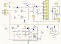
This circuit that works, but it works inconsistently. I am hoping someone can tell me how to prevent this brown-out from occurring.
This circuit works in my car from 12VDC. Car Ground, Battery 12V and Ignition 12V is attached to this circuit.
What this circuit does ...
The 555 is activated by a momentary push button. Activates the K2 relay and delivers 12V out to external timer device. After this external timer is finished. It sends a Ground, or 12V, constant back to my circuit which activates the K1 relay. The K1 relay powers up multiple 12v external devices.

The problem ...
Once the 555 activates the K2 relay, It's only after the external timer device sends the 12v or Ground signal that this brown-out occurs. I am thinking the brownout is occurred when K1 relay is activate. So I tried putting the 'C2' 47uF 50V cap in the circuit in hope to maintain voltage IF that was the problem.

This brownout does also happen. I would say half the time it happens. BUT ... if I start this circuit with the key and NOT the 555 circuit. Then turn off the the key. And THEN activate the 555 circuit, everything works, no brownout. If everything is off and wait 15 or 20 minutes, then activate the 555 circuit. Sometimes it will work, sometimes there's a brownout.

TONY
 

Attachments

Thread Starter

stillgrowingup

Joined Jul 15, 2015
219
What do you mean by "brownout"?
After the external timer device activates the K1 circuit. The 555 circuit SOMETIMES goes dead. Cutting power to external timer circuit, which shuts down the everything the K1 relay is powering. I thought that was called a 'Brown out', Sorry if not.

I know the circuit with the K1 relay works flawlessly with the external timer device.

Before I would have to turn my key to activate the timer. I know what to activate it from push button without needing the key, Plus still retain the option of activation with the key. Which everything seems to work as planned, with the exception of the 555 timer circuit cutting out .... sometimes.

Thanks

TONY
 

Dodgydave

Joined Jun 22, 2012
11,395
Your using the 555 timer as a Flipflop, i take it the power button puts a neg pulse on pin 2, and puts the relay K2 on and ledD7 (which is drawn the wrong way round). So the only way for it to flip back is to pull pin 6 high, or put a pulse on the reset pin4!!

I don't see the point of R8,C1 on the output of the 555??
 

Thread Starter

stillgrowingup

Joined Jul 15, 2015
219
Your using the 555 timer as a Flipflop, i take it the power button puts a neg pulse on pin 2, and puts the relay K2 on and ledD7 (which is drawn the wrong way round). So the only way for it to flip back is to pull pin 6 high, or put a pulse on the reset pin4!!

I don't see the point of R8,C1 on the output of the 555??
Dave

Thank you for the advice. I did correct the D7 led. Nice catch.

I removed R3 and R6 to prevent anything from hitting pin 4. Same problem.

I then removed R7 to prevent pin 6 from going high. I activated the 555 and the system did NOT (reset) "brownout" after the external timer activated the rest of the circuit. But ... I could NOT turn off the 555 timer once activated. I gradually increased the value of R7 till i reached 17.25K . At that value, the 555 timer was able to turn on and off by pushing the power button. And the 555 circuit did NOT (reset) "brownout". It seemed to work fine.

My next questions are ... do I simply replace R7 with a resistor value close to 17.25k? ... Do I change the value of R10? ....
With R7 value above 18.5K, I could NOT turn off the 555 circuit. With R7 value below 15K, the 555 circuit still (reset) "Brownout".

Without R8 and C1, I have a little bit of circuit debouncing happens when I push the trigger power button to activate the 555 circuit.

Tony
 
Last edited:

Alec_t

Joined Sep 17, 2013
15,120
Why have you used a PNP transistor for Q2?
What is the voltage swing of the signal driving its base?
Have you tried decoupling the supply voltage going to the 555 by using a diode and capacitor?
 

Thread Starter

stillgrowingup

Joined Jul 15, 2015
219
Why have you used a PNP transistor for Q2?
Q2 isolates the GND input trigger from the circuit.

What is the voltage swing of the signal driving its base?
The Base of Q2 receives a Full Ground from the external timer device. The Q1 and Q2 circuit has been working great for over a year now. :)

Have you tried decoupling the supply voltage going to the 555 by using a diode and capacitor?
No I have not ... I didn't think it was necessary. Should I have?

TONY
 

Thread Starter

stillgrowingup

Joined Jul 15, 2015
219
Leave R7 at 17k then if it works, also i would put a 1n4001 diode and a 1000uF smoothing cap for the 555 psu on pin 8 as said
Dave

1000uF is big wow :) ... Do I use a 16 V Electro ... or a Ceramic style cap? .. I have plenty of 1n4004 diodes, use I'll use those.

Since the 555 operation is flaky, it would prevent relay coil switching transients from affecting the 555 supply. DD has shown how to do this in post #8.
I amended my drawing with the changes you recommended. Please verify.

Thank you

TONYCapture.JPG
 

Dodgydave

Joined Jun 22, 2012
11,395
Put the diode in series with the batt supply to the 555, so that the resistors R7,10 and the reset pin are protected.
Use electrolytic caps, any value from 470uF.
 
Last edited:
Top