This circuit can't seem to work in simulators

Thread Starter

Artem2018

Joined May 15, 2018
4
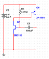
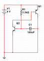
I was about to buy parts and solder them together, but I tried to simulate circuit first. None of the simulators doesn't do what they supposed to. Can somebody explain, is there an error in my circuit or simulators doesn't work?
 

Attachments

dl324

Joined Mar 30, 2015
16,788
Welcome to AAC!
None of the simulators doesn't do what they supposed to.
This sentence has two negations which becomes: All of the simulators do what they're supposed to.
Can somebody explain, is there an error in my circuit or simulators doesn't work?
Simulators need to know all component parameters before they can simulate. You're using a generic PNP and NPN transistor. What simulator are you using and how can it know what to do?

What do you think the circuit is supposed to do?
 

crutschow

Joined Mar 14, 2008
34,201
How can we determine why it doesn't work if you don't show us your results.
As dl324 said, put in real part number models for the transistors.
Then show us the full simulation schematic and results.
 

Thread Starter

Artem2018

Joined May 15, 2018
4
This sentence has two negations which becomes: All of the simulators do what they're supposed to.
Sorry, I don't know english very good. I'm not from english speaking country. I'll try to express my thoughts as good as I can.

Simulators need to know all component parameters before they can simulate. You're using a generic PNP and NPN transistor. What simulator are you using and how can it know what to do?
I'm using multisim.

What do you think the circuit is supposed to do?
I think it suposed to charge capacitor with low resistance from transistors. Then when capacitor is charged transistors are closed and capacitor is discharging. This process creates Spikes signals on q1 transistor collector. I hope what i said was correct and understandable.
 

dl324

Joined Mar 30, 2015
16,788
Sorry, I don't know english very good. I'm not from english speaking country. I'll try to express my thoughts as good as I can.
Are you using a translator to translate your native language to English?
I'm using multisim.
I think that simulator will show devices being destroyed. Did it do that for this case?
I think it suposed to charge capacitor with low resistance from transistors. Then when capacitor is charged transistors are closed and capacitor is discharging. This process creates Spikes signals on q1 transistor collector. I hope what i said was correct and understandable.
If you drew the schematic more conventionally, you might be able to see issues more easily:
upload_2018-5-15_8-33-22.png
 

Ian Rogers

Joined Dec 12, 2012
1,136
I think this is supposed to be a siren circuit and the inductor makes up the rest of the oscillator... Other wise the circuit doesn't do anything!!!
 
Top