Thevenin

Thread Starter

KCHARROIS

Joined Jun 29, 2012
312
Hello,

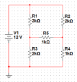
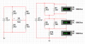
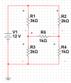
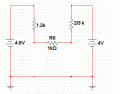
So I have bridge circuit like the one below where I'm trying to calculate the voltage across each of them using the thevenin approach to get R5.

Removing R5 to calculate voltage across the other 4 resistors is easy:

VR1 = 7.2 V
VR2 = 8V
VR3 = 4.8V
VR4 = 4V

Calculate Rth: Calculate Vth

Rth = (R1||R3)+(R2||R4)
Rth ≈ 1867.667Ω

Vth = 4.8V - 4V
Vth = 0.8V

Therefor VR5 is equal to:

VR5 = 0.8V * (1000Ω/(1000Ω + 1867.667Ω)
VR5 ≈ 0.279V//

But now the values across VR1, VR2, VR3, VR4 have changed how do I calculate them?

Thanks
 

Attachments

Thread Starter

KCHARROIS

Joined Jun 29, 2012
312
Ah see at first I thought that was it shteii01 but its not look closely at it again, your opinion might change. Remember the supply is replaced with a short it doesn't just disappear.

I can get to as far as getting the voltage accross R5 but I'm not sure what to do afterwards.
 

Attachments

shteii01

Joined Feb 19, 2010
4,644
Ah see at first I thought that was it shteii01 but its not look closely at it again, your opinion might change. Remember the supply is replaced with a short it doesn't just disappear.
Ok, I admit that I can be a bit dense at times.

Would I be correct in saying that voltage across R5 is voltage across R3 minus voltage across R4?
 

WBahn

Joined Mar 31, 2012
33,004
Hello,

So I have bridge circuit like the one below where I'm trying to calculate the voltage across each of them using the thevenin approach to get R5.

Removing R5 to calculate voltage across the other 4 resistors is easy:

VR1 = 7.2 V
VR2 = 8V
VR3 = 4.8V
VR4 = 4V

Calculate Rth: Calculate Vth

Rth = (R1||R3)+(R2||R4)
Rth ≈ 1867.667Ω

Vth = 4.8V - 4V
Vth = 0.8V

Therefor VR5 is equal to:

VR5 = 0.8V * (1000Ω/(1000Ω + 1867.667Ω)
VR5 ≈ 0.279V//

But now the values across VR1, VR2, VR3, VR4 have changed how do I calculate them?

Thanks
The key point that you are missing is that your equivalent circuit is ONLY equivalent in terms of the voltage/current characteristic at the terminals. NONE of the calculations pertaining to any of the other components remain meaningful beyond that.

If you wanted to, you could do five different Thevenin equivalent circuits, one for each resistor, to find the voltages across each resistor separately.
 

WBahn

Joined Mar 31, 2012
33,004
Ok, I admit that I can be a bit dense at times.

Would I be correct in saying that voltage across R5 is voltage across R3 minus voltage across R4?
Maybe, maybe not. Voltage is a signed quantity, so you need to define what polarity you mean when you say "voltage across (whatever)".
 

shteii01

Joined Feb 19, 2010
4,644
I can get to as far as getting the voltage accross R5 but I'm not sure what to do afterwards.
The next step is place the short in place of R5. Find the current in the short.

You have V open circuit, 0.8 volts. (I got the same by the way, if my method is right). It is also the Thevenin voltage source.

Once you have current in the short circuit, you calculate the Thevenin resistance, V open circuit divided by I short circuit.
 

Thread Starter

KCHARROIS

Joined Jun 29, 2012
312
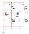
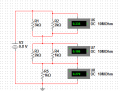
Wait I think I have it by finding Vth you find out the polarity of R5 (attached picture). This lets me know wether I should add or substract.

VR1 = 7.2V + 0.335V
= 7.535V
VR2 = 8V - 0.186V
= 7.184
VR3 = 4.8V - 0.335V
= 4.465V
VR4 = 4V + 0.186V
= 4.186V

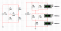
This correct according to the simulator.
 

Attachments

Tesla23

Joined May 10, 2009
560
Hello,

So I have bridge circuit like the one below where I'm trying to calculate the voltage across each of them using the thevenin approach to get R5.

Removing R5 to calculate voltage across the other 4 resistors is easy:

VR1 = 7.2 V
VR2 = 8V
VR3 = 4.8V
VR4 = 4V

Calculate Rth: Calculate Vth

Rth = (R1||R3)+(R2||R4)
Rth ≈ 1867.667Ω

Vth = 4.8V - 4V
Vth = 0.8V

Therefor VR5 is equal to:

VR5 = 0.8V * (1000Ω/(1000Ω + 1867.667Ω)
VR5 ≈ 0.279V//

But now the values across VR1, VR2, VR3, VR4 have changed how do I calculate them?

Thanks
I think people are being misled by thinking of 'one' thevenin equivalent.

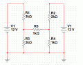
Replace the 12V and R1,R2 by one thevenin equivalent, and the 12V and R3,R4 by another, then you can simply calculate all the voltages.
 

Thread Starter

KCHARROIS

Joined Jun 29, 2012
312
Wait I think I have it by finding Vth you find out the polarity of R5 (attached picture). This lets me know wether I should add or substract.

VR1 = 7.2V + 0.335V
= 7.535V
VR2 = 8V - 0.186V
= 7.184
VR3 = 4.8V - 0.335V
= 4.465V
VR4 = 4V + 0.186V
= 4.186V
 

Attachments

shteii01

Joined Feb 19, 2010
4,644
I am getting a little confused.

Were you trying to find Thevenin equivalent circuit with respect to R5?

If yes, then I got Vth=0.8 V, Rth=2 kOhm.
 

Thread Starter

KCHARROIS

Joined Jun 29, 2012
312
Rth is not 2KΩ,

R1 and R3 are in parrellel giving a value of 1200Ω and R3 and R4 are in parrallel giving a value of 667.667, therefor Rth is equal to 1867.667Ω.
 

shteii01

Joined Feb 19, 2010
4,644
Rth is not 2KΩ,

R1 and R3 are in parrellel giving a value of 1200Ω and R3 and R4 are in parrallel giving a value of 667.667, therefor Rth is equal to 1867.667Ω.
I know that in my earlier post I tried to simplify the circuit and find Rth that way. I have abandoned that approach.

The way I found the Rth is that I solved for it the long way. I solved for V open circuit, Voc. Then I solved for I short circuit, Isc. Rth=Voc/Isc. That is how I got 2 kOhm.
 

WBahn

Joined Mar 31, 2012
33,004
As I understand the original post, he wants to find the voltages across EACH of the resistors. He started out by treating R5 as the load and finding the Thevenin equivalent for the rest of the circuit. He did that correctly finding that

Rth = (R1||R3)+(R2||R4) = 1867Ω

Vth = V1*R3/(R1+R2) - V1*R4/(R2+R4) = 4.8V - 4.0V = 0.8V

(Vth is positive on left side of R5)

Then the voltage across R5 is

V5 = Vth*R5/(Rth+R5) = 279mV

Now, what he wants to know is how to get the rest of the voltages across the rest of the resistors.
 

Thread Starter

KCHARROIS

Joined Jun 29, 2012
312
Wbahn, that's exactly what I want to do. Before thevenizing the circuit I removed R5 and calculated the voltage across the R1 through R4. I then thevenized the circuit and you get something like the attached photo. Now knowing the polarity of that resistor I either subtract or add 0.186 to R2/R4 and either subtract or add 0.335V to R1/R3 all from original values calculate with R5 removed. Is this a correct method???

VR1 = 7.525V
VR2 = 7.814
VR3 = 4.465V
VR4 = 4.186V
VR5 = 0.279V
 

Attachments

Tesla23

Joined May 10, 2009
560
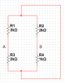
Why don't you redraw the circuit like this before you find your thevenin equivalents?


Isn't that easier? You can easily calculate all the voltages.
 

Attachments

WBahn

Joined Mar 31, 2012
33,004
Wait I think I have it by finding Vth you find out the polarity of R5 (attached picture). This lets me know wether I should add or substract.

VR1 = 7.2V + 0.335V
= 7.535V
VR2 = 8V - 0.186V
= 7.184
VR3 = 4.8V - 0.335V
= 4.465V
VR4 = 4V + 0.186V
= 4.186V

This correct according to the simulator.
While I suspect this method is valid, at least for this topology, it is not at all obvious to me that it has to be, especially in the general case. I'll have to play with it some to prove that it is, indeed, valid and why.

Certainly is it true that, if Va is the voltage on the left of R5 and Vb is the voltage on the right, that if Vab > 0 then the voltage at Va drops and the voltage at Vb rises in response to R5 being placed across Vab.

So

Va' = Va + ΔVa (and we know ΔVa < 0)
Vb' = Vb + ΔVb

It is also true that the new Vab = VR5, the result from the analysis.

VR5 = Vab' = (Va + ΔVa) - (Vb + ΔVb)

VR5 = (Va - Vb) + (ΔVa - ΔVb)

We know that Va-Vb is Vth

VR5 = Vth + (ΔVa - ΔVb)

And thus we know that

(ΔVa - ΔVb) = VR5 - Vth

What is not obvious is how we determine ΔVa and ΔVb individually. This will probably come in the form of a relationship that gives us (ΔVa + ΔVb), but I'm not seeing it by casual inspection.

I'm suspecting that this method may only work for specific topologies, such as the classic bridge circuit we have here.
 

WBahn

Joined Mar 31, 2012
33,004
Why don't you redraw the circuit like this before you find your thevenin equivalents?


Isn't that easier? You can easily calculate all the voltages.
I'm not seeing how that makes them any easier to calculate. I'm probably just not looking at it right to have the, "Ah hah!" moment.
 

WBahn

Joined Mar 31, 2012
33,004
Here is the equivalent circuit from which you can readily calculate the voltages at each end of R5

Ah hah!

Okay, I see what you are getting at. Because each side now has a Thevenin equivalent in which one port is ground, we can find not only the voltage across R5, but actually the voltages of each side relative to ground.

I agree that that is a good way to go and, frankly, not one I would have likely thought of. But it seems like a good approach when you can see a way to break the circuit up that way. Don't know how often that is possible, though.
 
Top