Yes.
But with the advice and free circuits you have been given over the last 180 posts, you could also achieve good sound quality, good efficiency and good reliability.
I can't put the whole board to waste since it has a battery detector and a VU unit. So I'll have to use a voltage regulator and see what happens. Hopefully after all changes the only thing getting super hot is the regulator. Then again I did tests on my test board (breadboard) involving 1N914 diodes and only things getting hot are tip41's while tip42's were warm. So i'll change those diodes to 1N4001 and see what happens.
Now I did notice that the voltage at the point between the 2 resistors that connect VCC to TIP41's base can be higher by about 50% while music is playing. I'm wondering if those bootstrap capacitors are a bad idea or if theres a better way to calculate max voltage at that point then maybe I can pick better resistors
Good volume from your fairly small speakers means using lots of amplifier power that you do not have.
Since your amplifier circuit is simple and does not have matched transistors like in an IC amplifier or in a simulation, then you need to fiddle with resistances to get the most fairly low distortion power from the amplifier.
But with the unbridged design I did last week I got good volume at 7.2V for 90 consecutive minutes with some heating, but not to the point where the parts malfunctioned and then I was using TIP41/42 transistors as well. Even these circuits I'm doing now may give even better volume but overheating is an issue because its incremental and was actually hot to the touch at one point and sometimes with a very faint rubbery smell. In my last design it did not have that smell. But people say you can get more power from bridging. What if somehow I could scale all of the resistors (say multiply each resistor by a certain value) to the point where I get maximum audio without incremental heat? Maybe there's that hidden threshhold I have constantly exceeded in my latest circuit.
Now I did notice that the voltage at the point between the 2 resistors that connect VCC to TIP41's base can be higher by about 50% while music is playing. I'm wondering if those bootstrap capacitors are a bad idea or if theres a better way to calculate max voltage at that point then maybe I can pick better resistors
I turned up the voltage gain with the R1 and R2 resistors until the output was almost at clipping.
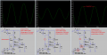
Then I changed R1 for symmetrical clipping and adjusted R1 and R2 again for almost at clipping again. Fiddling back and forth until here is how well Bootstrapping improves output power and reduces distortion:
But with the unbridged design I did last week I got good volume at 7.2V for 90 consecutive minutes with some heating.
Is there a setting where I get maximum audio without incremental heat?
Maximum audio output power occurs when each amplifier half is biased for symmetrical clipping.
Extra heating in the output transistors occurs when the DC output voltage from each half amplifiers are not identical because then the speaker and output transistors have DC current in them.
Maximum audio output power occurs when each amplifier half is biased for symmetrical clipping.
Extra heating in the output transistors occurs when the DC output voltage from each half amplifiers are not identical because then the speaker and output transistors have DC current in them.
I also noticed in the sim that the waveform is different when I changed the decoupling capacitor across the battery from 22uF to 2200uF. But I'm curious as to why you only chose 470uF.
A resistor in series with the speaker will waste battery power by making heat only if the two amplifier halves are badly adjusted wrongly with different DC voltages at their outputs. When the amplifier output halves are adjusted to have identical DC voltages then the speaker has no DC current in it not provided by the transistors.
Of course a resistor in series with a speaker reduces the speaker output power and reduces damping of speaker resonances.
Instead, replace one of the two series diodes with a resistor selected to produce an idle current of 10mA to 30mA in each pair of output transistors.
That idea is tough.
I tried this in sim in both amps and tested with 5V and 8V...
replaced 2 diodes with 1 diode and 1 resistor. Resistor value of about 33 ohms gives about 3mA which is nice, but at 5V, the waveform looks like crossover distortion in the middle. Then I increased the resistance at 5V and the crossover distortion is removed, but when I raised the voltage back to 8V, the current is now at least 200mA which is an all-time new high.
When I replaced the 2 diodes with a resistor by itself, the values I had to use were slightly above triple (like about 120 ohms) to notice the same effects.
I often wondered about replacing one of the NPN base resistors with a diode...

 Facebook
 Google
 GitHub
 Linkedin