The "infamous" 555 servo controller

Thread Starter

abc27

Joined Dec 16, 2010
50
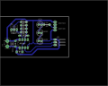
That's really strange. I etched and drilled a completely different layout to that.

I suppose i'll have another crack at it then...


That's the layout I used. I think I may have a mirroring issue as you said, i'll try again and see what happens.
 

Attachments

jpanhalt

Joined Jan 18, 2008
11,087
A mirroring problem can't be fixed for all practical intents. You will need to start over. Sorry, I grabbed the draft instead of the final layout. They are virtually the same with a few refinements to widen traces -- I usually use copper pours for that purpose.

After you make your transfer to the board, hold it up and with imaginary X-ray vision, see if the servo pins seem right relative to where the fixed resistors and diode are on the board..

John
 

Thread Starter

abc27

Joined Dec 16, 2010
50
Working on the new PCB at the moment. Etching took me only two minutes thanks to an almost sludge like boiling hot etching solution and my makeshift needle drill worked brilliantly.

Here's hoping it works...

BTW are you certain the 555 used in the previous circuit is dead?
 

jpanhalt

Joined Jan 18, 2008
11,087
I assume you are using ferric chloride. I heat mine to about 60°C. I would not recommend going much higher. You will certainly get more nasty fumes at a higher temperature. Those fumes contain HCl, from a reaction of FeCl3 and water, and will probably lead to an earlier death for your bath. Moreover, the fumes are quite corrosive, and you will notice their effects, if you haven't already. Yes, you can replinish it with liquid HCl, but do you know how much to add? Too much HCl is not good either.

John
 

Thread Starter

abc27

Joined Dec 16, 2010
50
I assume you are using ferric chloride. I heat mine to about 60°C. I would not recommend going much higher. You will certainly get more nasty fumes at a higher temperature. Those fumes contain HCl, from a reaction of FeCl3 and water, and will probably lead to an earlier death for your bath. Moreover, the fumes are quite corrosive, and you will notice their effects, if you haven't already. Yes, you can replinish it with liquid HCl, but do you know how much to add? Too much HCl is not good either.

John
I etched under an extractor fan. I may not be excellent at electronics but I know my chemistry at least :)

Edit:
Well, it appears as if i've made the exact same error again. I haven't actually soldered anything to the board yet, is it salvageable or is it back to the etching tank ?
 

jpanhalt

Joined Jan 18, 2008
11,087
The 555 doesn't have a plane a of symmetry. So my guess, without much thought, is no. Why not do it right and save the neurons. You only have so many good thoughts in this world. Why waste them.

I'll think more about it tomorrow. What are you doing up this late messing with a silly PCB? I think I hear your wife. Oh, honey, where are you?

John

Edit: Then, again, on second thought, I would try it. But be sure the 555 pins are correct as to ground and V+.

John
 

Thread Starter

abc27

Joined Dec 16, 2010
50
Well i've just finished work on a new PCB.

Still dead. Completely and utterly dead. I am at a complete loss as to what i'm doing wrong. How many attempts are necessary to get a simple 555 board working? :(

The strange thing though is that when I connect a multimeter to the POS and NEG ends of the PCB I get a reading on the multimeter, wouldn't that indicate that the circuit is functional?

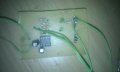
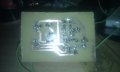
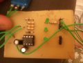
I've attached pictures.
 

Attachments

Thread Starter

abc27

Joined Dec 16, 2010
50
I'm checking the board for continuity and oddly enough there appears to be no issues. Thus far i've checked the LED and the DC motor section of the board
 

Thread Starter

abc27

Joined Dec 16, 2010
50
There was one bad joint that I resoldered.

There appears to be continuity throughout as I placed the test probes on the POS and NEG battery pads and I get a resistance reading of about 8 ohms.
 

jpanhalt

Joined Jan 18, 2008
11,087
I can't see anything clearly in the pictures. Looking at the board with the servo pins on your right, is the dark band on the diode on the left near pin 8 or right near pin 5? Show the potentiometer.

What are the two big capacitors? They look like electrolytics. What are their values?

Finally, turn off the flash on your camera. I can't see anything clearly in either picture with all the glare. Find a way to hold the camera still or use natural light. If you have a way to clean the flux residue on the board, that will help see what's connected to what. If it was water soluble flux, use water. If it was rosin flux, use denatured alcohol (shellac thinner) or isopropyl alcohol that is at least 90% alcohol.

John
 

Thread Starter

abc27

Joined Dec 16, 2010
50
I can't see anything clearly in the pictures. Looking at the board with the servo pins on your right, is the dark band on the diode on the left near pin 8 or right near pin 5? Show the potentiometer.
It's pointing towards pin 5.

What are the two big capacitors? They look like electrolytics. What are their values?
They are. The one to the left of the 555 is 100μf and the one beneath it is 22μf.

Finally, turn off the flash on your camera. I can't see anything clearly in either picture with all the glare. Find a way to hold the camera still or use natural light. If you have a way to clean the flux residue on the board, that will help see what's connected to what. If it was water soluble flux, use water. If it was rosin flux, use denatured alcohol (shellac thinner) or isopropyl alcohol that is at least 90% alcohol.

John
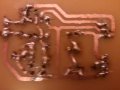
I've attached two new photos. They're a bit blurry but my camera is terrible in low-light conditions.
 

Attachments

Thread Starter

abc27

Joined Dec 16, 2010
50
Some minor success. The LEDs appear to be working as is the switch. The DC motor isn't working but the servo motor is receiving power but still not responding to signal.


Edit:
And now they've stopped working...
 

Thread Starter

abc27

Joined Dec 16, 2010
50
I think I may have a clue as to what may be going on.

I've been checking the board for continuity the past while. Most of it gives me back a reading of 0.01 ohms or so which is perfect. However the section with the pads for the motor and switch is giving me 13ohms which I think is affecting the rest of the circuit. I'm going to try and resolder it and see how I fare.
 

jpanhalt

Joined Jan 18, 2008
11,087
Why did you switch from 22 nF to 22 uF? That is 1000X bigger. It won't work. You need a 22 nF capacitor there. Your old one is OK to use. Replace it and see what happens. If it still doesn't work, do the following.

Be sure that both copper traces on the servo ground lead are soldered to the pin. I can't tell, if there are gaps.

For the pot, be sure there is not a bridge/short between the center pad and pad closest to the resistors. Disconnect the battery, short positive and negative together with a small resistor (1K or less), and remove the 555 chip. You can undo the short. Then put your ohmmeter to pin 7 of the socket and the other lead to the 56K resistor lead nearest the pot leads, the resistance should change as you turn the pot. What range do you see?

Test the resistance between pin 6 and 7. If you have a diode check function, use it. Otherwise, check with the red to 7 and black to 6, then the other way around. What do you see?

John
 

Thread Starter

abc27

Joined Dec 16, 2010
50
YYYYYYYYYYYEEEEEEEEEEEEEEEEESSSSSSSSSSSSSSSSSSS!!!!!!!!


Success at long last. The servo works, as does the DC motor and the switch. The only problem is with the LEDs. They don't light up when the motor is running. I guess you can't have everything in life.

I got that 22uF cap today, I asked for 22nF but they must have made a mistake at the shop. So I just soldered back in my old polyester cap and it worked!

I just can't believe it! It took me 2 months but I finally got it! All thanks to you John, you were an unbelievable help throughout!

Thank you!
Michael
 

Thread Starter

abc27

Joined Dec 16, 2010
50
..........


And it stopped working again. DC Motor and switch are still operating perfectly well. The servo now just makes a buzzing sound.

Edit:

And now it's working again. I must have a short or loose connection somewhere.
 

jpanhalt

Joined Jan 18, 2008
11,087
The motor may be drawing enough current to drop the V+ rail voltage. Put your voltmeter to the V+ near the 555 and see if it stays at 6V.

John
 

Thread Starter

abc27

Joined Dec 16, 2010
50
Hey everyone... It's been a while.


I've got a small problem. When I turn on the DC motor the servo starts juddering. It's not really a massive problem but if there's a way of fixing that without remaking the circuit, i'd love to know it. Personally I think it's as jpanhalt said in the last post. The motor is drawing so much current that the voltage is dropping.

Supply voltage drops to 3V once the DC motor is switched on.
 
Top