Facebook
 Google
 GitHub
 Linkedin
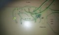
555 timers MUST have:
1) An 0.1uF (100nF) capacitor across the Vcc and GND terminals.
2) A 1uF or larger cap across the Vcc and GND terminals.
These are not optional. If they are omitted, you will have problems.
I see that you have a 100nF cap, but no 1uF or larger cap.
1) An 0.1uF (100nF) capacitor across the Vcc and GND terminals.
2) A 1uF or larger cap across the Vcc and GND terminals.
These are not optional. If they are omitted, you will have problems.
I see that you have a 100nF cap, but no 1uF or larger cap.