The Fading RGB LED

Thread Starter

campeck

Joined Sep 5, 2009
194
Hello again!

Even though I haven't quite figured out my last LED thingy I thought I would ask this. I am trying to get an RGB LED to randomly fade in and out of all colors with minimum board real estate available.


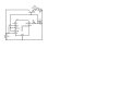
I have seen this circuit by Audioguru and was wondering first if someone could walk me through it's operation. I have a basic understanding of feedback and opamps but I would leave it at basic.

Secondly could you use comparators instead of opamps? If so I have a LM339.

Thanks!

I was thinking there is another easy way to fade the LED. using a capacitor in parallel with the LED but I have noticed it only fades one way and either turns on or off abruptly. How to make it fade in AND out like in this video. I thought I saw the connections correctly but My circuit didn't work like his.
http://www.youtube.com/watch?v=_Blg8T0DWtU
 

Wendy

Joined Mar 24, 2008
23,421
There are several ways to do this. The circuit your showing is a triangle wave generator, the triangle wave is fed to the LED, which causes the effect.

I've built a bunch of simple 555 timers that light up a pair of LEDs for a couple of seconds, then go out for slightly longer. I built over 30 of the suckers, adding wire with clips so they can chain together. The idea is to put them in a bush with one 9V battery powering them all. I call them bush goblens, and the effect is excellent.
 

Audioguru

Joined Dec 20, 2007
11,248
An opamp has an output that goes both high and low. It has frequency compensation inside so it can use negative feedback to control its gain.

A comparator has an open collector at its output that goes low. A pullup resistor is needed at its output to make it go high.
It does not have frequency compensation so cannot have negative feedback to control its gain.
 

Audioguru

Joined Dec 20, 2007
11,248
There is a schematic in one of the datasheets that shows a comparator with a pile of parts added (a huge capacitor at its output to ground) that kills its oscillation so it can be used as a very slow amplifier.
 

Wendy

Joined Mar 24, 2008
23,421
Another possible way...


I haven't built it, but just finished drawing it for another thread. These projects seem to come in groups.

R1 is the cycle rate (how many seconds a flash lasts), and R2 is the fade rate. If R3 is adjusted to 91Ω it can go down to 6V with no problem, it may even manage 5V (R3=39Ω). It will go to 3 seconds per flash to faster than the eye can see, Set both pots for max before powering up, and don't take R1 to it's minimum value or the 555 will get hot.

This is a variation of the 555 Hysteretic Oscillator, R2 and C2 both slowly charge and discharge, Q1 and Q2 are basic transistors, 2N2907 or 2N3904 (almost any PNP transistor) will work.
 

Thread Starter

campeck

Joined Sep 5, 2009
194
I will build it tomorrow!
what do you recommend for Q1 and 2?
I have numerous 2n3904 type PNP and NPN transistors and a darlington TIP120

I also have a NE555 and CMOS versions.
 

SgtWookie

Joined Jul 17, 2007
22,230
Q1 and Q2 are PNP transistors. You could use 2N2907, 2N3906, 2N4403, and many other general-purpose PNP transistors.

You could also use TIP Darlington transistors, as long as the part number ends in 5, 6, or 7, which are PNP.
TIP Darlington transistors that end in 0, 1, or 2 are NPN, and are not suitable for this project.

R1 needs to have at least a 150 Ohm resistor in series with it. Otherwise, if R1 is set near to 0 Ohms, it will probably get fried.
 

Wendy

Joined Mar 24, 2008
23,421
Sorry Wook, the TIP series won't work, they need to be descrete transistors. This is because the TIP105 etc. have internal resistors. Could be wrong about this, but don't think I am. I'm not where I can check at the moment.

Since the rate of flash will be slow I elected not to put the resistor in series with R1. By the time you hit 150Ω the sucker is flashing so fast you can't see anything, and with a fresh 9V the 555 gets hot, but it won't blow. Found this out the hard way. If the battery is the least bit used the 555 won't even get warm. With a serious power supply you'd probably pop the top off. BTW, the same logic also applies with R2.

OK, I was able to look up fairchild's data sheet. Check it out.

http://www.fairchildsemi.com/pf/TI/TIP105.html
 
Last edited:

Thread Starter

campeck

Joined Sep 5, 2009
194
alright,
I didn't get around to building it today, But I went to radio shack and picked up some goodies and got a box of samples from stmicro. It's like Christmas!
 

Thread Starter

campeck

Joined Sep 5, 2009
194
Hey Bill,

Your circuit works great on 5v. I am wondering what determines the duty cycle here? It looked like it or the frequency was varying.
So the timing capacitor charges and discharges through R1 and the output pin and C2 through R2 and the output?

There is a downside to this circuit with all the big capacitors needed to drive three colors.
Although I will build it anyway for practice and show you guys.

The next circuit I try will be audiogurus.
And since I have a quad op-amp it should keep parts down.

Thanks!
 

Wendy

Joined Mar 24, 2008
23,421
I've posted this on several threads, started building one myself. There are some alternate ways to build it without too much heartburn. Use a CMOS 555, up R1 and R to 100KΩ, and downsize C1 and C2 to 22µF. If you can't get the flash rate slow enough (it should be identical) then use 47µF.
 

Wendy

Joined Mar 24, 2008
23,421
Don't know, it looks like it would work, but differently. I've never seen that configuration before, pin 4 is usually not part of the oscillator. It will flash much faster, and the LED will be a bit dimmer at it's maximum brightness. My circuit aimed for 20ma, this one goes for 13ma. Nice thing about protoboards though, the stuff is 100% resuable, build one and see.

Another variation on the design, Wookie suggested it at one point. I rejected it because while it would work it dosn't have the same controlability. You seem to indicate you don't like the parts count, which I do empathise with.


I transistioned to the larger resistors and smaller caps I mentioned earlier that could be used in the previous design. Again, a CMOS 555 would probably work, and overall the circuit would draw much less current. This design, as with the previous, is capabile of going much slower, faster is usually not a problem.

BTW, if you use RGB LEDs, you can reconfigure this pretty easily for common anode or common cathode. Common cathode would require NPN transitors though.
 

Thread Starter

campeck

Joined Sep 5, 2009
194
That last photo was incorrect. He drew the circuit wrong.
This is how to configure it.
Is there any way to change duty cycle here?
I like the parts count of this circuit. But the LED does look pretty dim...
 

Attachments

SgtWookie

Joined Jul 17, 2007
22,230
Is there any way to change duty cycle here?
Use a pot connected between pin 5 and ground, resistance between 5k (min) and perhaps 50k.
With nothing connected to pin 5, default threshold/trigger levels are 1/3 Vcc and 2/3 Vcc. The lower the resistance between pin 5 and ground, the lower both thresholds become.
I like the parts count of this circuit. But the LED does look pretty dim...
Decrease R2 somewhat.
With a bjt 555, you'd be better off using a PNP transistor with the LED & resistor connected between the emitter and Vcc.
 

Thread Starter

campeck

Joined Sep 5, 2009
194
I just realized the fixed version of the youtube circuit is basically that last circuit you have there Bill.
I made the changes to the previous circuit you gave with 555cmos and 100k and 22uF
But to change the duty cycle I put a diode in series with the 100k for discharge and a diode in series with a 47k for charge. (those both in parallel at R1)

I will build your second circuit after fiddling with this one.

SGTWOOKIE

what do you mean by bjt?

I will try the 5 pin way since I have yet to mess with this feature of the 555.
Do the threshold and trigger go down while keeping the same ratio? or do they go down linearly?
 

Wendy

Joined Mar 24, 2008
23,421
BJT = Bipolar Junction Transistor, a normal transistor.

Pin 5 was originally meant to allow noise imunity for a 555, but it can also be used to set one of the trip points. A 555 has trip point 1/3 and 2/3 Vcc, one of them can be adjusted.

I've shown the link, but if you want to understand how the 555 Hysteretic Oscillator article also has a theory of operation.
 
Top