The bsf LATx issue

Thread Starter

MaxHeadRoom

Joined Jul 18, 2013
30,808
I had some routines that had come up from the 16f days and had such I/O instructions as bsf/bcf PORTx and when using them in a couple of 18f series, as they seemed to work OK I didn't get around to changing them to bsf LATx etc.
I recently went from a 18f2221 to a 18f23k22 and no I/O seemed to be working.
I attached a led strip to a port and did a bsf PORTx, 0 to 7, stepped in turn
The port LED would switch on, but any subsequent bsf PORTx would turn the bit on at the same time the previous one would turn off resulting in the last one only being on.
The bsf LATx cured the problem with all being on at the last step.
I just wondered what the difference would be between two very close chips?
Max.
 

ErnieM

Joined Apr 24, 2011
8,415
Tisk tisk, such scant information. :(

Which port? Using what code?

Generally *any* port configured as analog may also be set as a digital output. One may freely set or reset such pins at will and they Do respond properly.

However, any attempt to read the port value from a pin in analog mode returns a zero.

Latch pins operate off to the side of the port and are not subject to this limitation.

While I kinda doubt the code was in error had you supplied the port info then I could show you what needed to be turned off.
 

Thread Starter

MaxHeadRoom

Joined Jul 18, 2013
30,808
Both using PA and PC. output only.
It was a LCD output routine that used 4 bits for data RA0-3 and RC3,4,5 for control.
Simple bsf PORTA, 0 etc.
The analog ports were turned off
ANSELA, B, C cleared.
I can post the code but thought there may be reason for an obvious difference between the 2221 and the 23k22?
Max.
 

THE_RB

Joined Feb 11, 2008
5,438
I'm going from memory but have a recollection of a similar issue.

Writing to the PORT did not change the output pins. I had to write to the LAT.

From memory that was how i realised I had accidentally written to PORT not LAT.

Maybe it's in the hardware? You could check the errata sheet.
 

Alberto

Joined Nov 7, 2008
169
In 23K22, direct pin writing will NOT work at higher OSC frequencies due to R-M-W issues.
And will NOT work at all with the pins set to Analog mode. You have to write to the Lat register, using Latx.x.

Alberto
 

Thread Starter

MaxHeadRoom

Joined Jul 18, 2013
30,808
In 23K22, direct pin writing will NOT work at higher OSC frequencies due to R-M-W issues.
Alberto
Thanks Yes I was beginning to realize that, I am running at 20mhz.
I am re-writing the routines and in the process use the more efficient instructions of the 18F. to make it a bit tighter code.
Max.
 

ErnieM

Joined Apr 24, 2011
8,415
In 23K22, direct pin writing will NOT work at higher OSC frequencies due to R-M-W issues.
Extraordinary claims require extraordinary proof, or at least cite a source for this information.

Let's look at the data sheet:


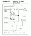
What few understand is there are not separate port and latch registers, there is just one register. No "shadow" register and output register, just one register marked "Data Latch".

The difference is latch reads this register directly, and port reads the pin.

If one has successfully managed the pin state as no analog, digital out, and there are still R-M-W issues when setting pins there are a few things to cause this:

Check if anything is pulling down the pin so it reads as a logic zero.

Check if your code is immediately setting one port pin then another in turn. You must allow time for a pin to get to reach the new value.

(THAT is why I asked for schematic and code... the devil is always in the details)
 

Attachments

Thread Starter

MaxHeadRoom

Joined Jul 18, 2013
30,808
After the original code did not transfer over to the 23k22 I just entered a test program with LEDs on the outputs and used the Step-Into feature of the ICD so there was plenty of time between bit set functions.
I also monitored all registers on the Watch screen.
The previous test is with PORTx instead of LAT, shown commented out.
The bsf LATx worked OK.
Max.

Rich (BB code):
      LIST      P=PIC18F23K22          ; list directive to define processor
     #INCLUDE <P18F23K22.INC>         ; processor specific variable definitions

     ;Setup CONFIG1H
         CONFIG FOSC = HSHP, PLLCFG = OFF, PRICLKEN = OFF, FCMEN = OFF, IESO = OFF
     ;Setup CONFIG2L
     CONFIG PWRTEN = OFF, BOREN = OFF, BORV = 190
     ;Setup CONFIG2H
     CONFIG WDTEN = OFF, WDTPS = 1
     ;Setup CONFIG3H
     CONFIG MCLRE = EXTMCLR, CCP2MX = PORTB3, CCP3MX = PORTC6, HFOFST = OFF, T3CMX = PORTB5, P2BMX = PORTC0
     ;Setup CONFIG4L
     CONFIG STVREN = OFF, LVP = OFF, XINST = OFF
     ;Setup CONFIG5L
     CONFIG CP0 = OFF, CP1 = OFF             ;CP2 = OFF, CP3 = OFF
     ;Setup CONFIG5H
     CONFIG CPB = OFF, CPD = OFF
     ;Setup CONFIG6L
     CONFIG WRT0 = OFF, WRT1 = OFF            ;, WRT2 = OFF, WRT3 = OFF
     ;Setup CONFIG6H
     CONFIG WRTB = OFF, WRTC = OFF, WRTD = OFF
     ;Setup CONFIG7L
     CONFIG EBTR0 = OFF, EBTR1 = OFF        ;, EBTR2 = OFF, EBTR3 = OFF
     ;Setup CONFIG7H
     CONFIG EBTRB = OFF

;------------------------------------------------------


    #define    LCD_D4        PORTA, 0    ; LCD data bits
    #define    LCD_D5        PORTA, 1
    #define    LCD_D6        PORTA, 2
    #define    LCD_D7        PORTA, 3


    #define    LCD_D4_DIR        TRISA, 0    ; LCD data bits
    #define    LCD_D5_DIR        TRISA, 1
    #define    LCD_D6_DIR        TRISA, 2
    #define    LCD_D7_DIR        TRISA, 3
      
    #define    LCD_E            PORTC, 3    ; LCD E clock
    #define    LCD_RW         PORTC, 4    ; LCD read/write line
    #define    LCD_RS        PORTC, 5    ; LCD register select line
    
    #define    LCD_E_DIR        TRISC, 3    
    #define    LCD_RW_DIR        TRISC, 4    
    #define    LCD_RS_DIR        TRISC, 5    
    
    #define    LCD_INS        0    
    #define    LCD_DATA        1
    
        cblock    0x000
        COUNTER        ;res    1
        delay        ;res    1
        temp_rd        ;res    1
        temp_wr
        variables    ;UDATA
        ptr_pos        ;RES 1
        ptr_count    ;RES 1
        temp_1        ;RES 1
        temp_2        ;RES 1
        temp_3        ;RES 1
        LatchPA
        Nibble


        endc

        org    0x0000

    goto    start
    NOP
    NOP
    NOP
;PROG1     CODE


start:    
        clrf        Nibble
        clrf        LatchPA
        clrf        ANSELA
        clrf        ANSELB
        clrf        ANSELC
        clrf         CM1CON0
        clrf        LATA
        clrf        LATC
        clrf        TRISA
        bcf         LCD_E_DIR
        bcf        LCD_RW_DIR
        bcf        LCD_RS_DIR ;     TRISC
        bsf        LATA, 0        ;LCD_D4
        bsf        LATA, 1        ;LCD_D5
        bsf        LATA, 2        ;LCD_D6
        bsf        LATA, 3        ;LCD_D7
        bsf        LATA, 4
        bsf        LATC, 3        ;LCD_E
        bsf        LATC, 4        ;LCD_RW
        bsf        LATC, 5        ;LCD_RS
        bcf        LATA, 3
        movff        LATA,         LatchPA
        movlw        0xf0
        andwf        LatchPA, F
Stop:
        goto Stop        
        end
 

Thread Starter

MaxHeadRoom

Joined Jul 18, 2013
30,808
Well, the LATx ports were included in the 18F family for a reason. Precisely to cope with the RMW issue.
Yes I had read this many times, just that I was curious that it had seemed to have worked with a couple of other 18F's, in fact some of the code came from the 18f files CD supplied with the Picdem-2 board from Picmicro?.
I have pretty much changed all the routines over now so it should be no problem.
Max.
 

NorthGuy

Joined Jun 28, 2014
611
Extraordinary claims require extraordinary proof, or at least cite a source for this information.
I guess he wanted to say that if you write to a PORT/LAT, then read back PORT with very next command, the result of the previous command may not yet be in effect.

As with the OP's code:

; assume PORTA is all zero
bsf PORTA, 0 ; reads all zeroes, sets bit 0, writes back
bsf PORTA, 1 ; still reads all zeroes!!! sets bit 1, writes back

This can only happen when OSC frequency is high, because at low frequency there will be enough time for the pin to go high between commands.

OP switched to higher frequency and voila ...
 

Thread Starter

MaxHeadRoom

Joined Jul 18, 2013
30,808
True the original code was written for a lower clock rate, I used 20Mhz.
I guess the moral to the story is always use LATx to write if you got em.
Although it did work on the 18f2221 with the higher clock?
Max.
 

THE_RB

Joined Feb 11, 2008
5,438
That code is nasty!

You should shadow the LCD data bits D4-7, and RS too (in a RAM variable), then write those 5 bits to the port as one MOVFF instruction. Fast and no RMW issues.

Then allow DATA pin settling time with some NOPs, then clock the LCD E pin / and \ again with a few nops in there as well.

The newer PICs use a finer process technology with smaller drive FETs on the output pins, so the digital pins won't drive as much output current (and have a higher Rds-ON pin resistance). To drive the LCD pins and wiring capacitance etc you need some delays for pin settling time.
 

NorthGuy

Joined Jun 28, 2014
611
You should shadow the LCD data bits D4-7, and RS too (in a RAM variable), then write those 5 bits to the port as one MOVFF instruction.
Why? It only matters what the data bits are when you cycle E and it doesn't really matter in what order and how you set or clear them.

If you move 5 bits with a MOVFF instructions, this will inadvertedly change other 3 bits as well. Therefore, you will create problems for all other tasks that may operate on the corresponding 3 pins.
 

NorthGuy

Joined Jun 28, 2014
611
Read the port first and OR it with the Data bits then MOVFF it back.
Not that easy. You read your port (that is lat), then an interrupt happens, the interrupt writes something to the port, then the interrupt returns, and then you overwrite the bits that were set/cleared during the interrupt with your MOVFF instruction.

Consequeces? Your H-bridge works perfectly but once a week or two the H-bridge burns down. Why would that be? An interrupt happened just in the right (wrong) time, and MOVFF from the display code shorted the H-bridge.
 
Last edited:

THE_RB

Joined Feb 11, 2008
5,438
Why? It only matters what the data bits are when you cycle E and it doesn't really matter in what order and how you set or clear them.
It matters when you get a hardware RMW issue. :)


If you move 5 bits with a MOVFF instructions, this will inadvertedly change other 3 bits as well. Therefore, you will create problems for all other tasks that may operate on the corresponding 3 pins.
Not really. I generally run 6 LCD pins on LATB; 4data, RS and E. Writing all togther for data means writing 6 digital outputs, writing 0 to E at that time of course.

The other two pins are the USART TX/RX which in my case are almost always in use and under control of the USART hardware, so writing to the entire LATB does not cause an issue as it does not affect these two remaining pins.

Your mileage may vary. :)
 

NorthGuy

Joined Jun 28, 2014
611
It matters when you get a hardware RMW issue. :)
LATx doesn't seem have any RMW issues. Even if you think it does, adding nop should cure it.

Your mileage may vary. :)
I don't like restricting where I can connect things. I just have a general code which would work with any pins. It is in a separate file. I only need to include the file and define where the pins are and it automatically works. Can use any pins without restriction. It uses pins that I want it to use and it doesn't produce any side effects.
 
Top