Testing feedback functionality of an analog controller

Thread Starter

yef smith

Joined Aug 2, 2020
1,447
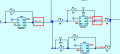
Hello,I have built an LTspice simulation of a PID controller based on this youtube video.

The basic schematic is presented. The AD797 model was used to construct all the blocks.

A PID controller was built by the schematic and the AC response is presented.

I tested with AC response each stage but I don't want to overwhelm with plots.

Basically I am used to test my circuit in AC response, but it doesn't say much to me.

In AC response we test stability and gain but the PID is designed to do feedback.

What method is used to test the PID feedback capabilities?
LTspice files are attached.


PID_shem.PNG
PID_plot.PNG
 

Attachments

crutschow

Joined Mar 14, 2008
38,325
To be meaningful, the PID circuit must be in a loop with PID values selected to stably control the item/process of interest.
By itself, the test of a PID circuit has no significance, other than to show the P, I, and D responses of the selected component values, which in this case, are arbitrary.
 

LvW

Joined Jun 13, 2013
1,998
In principle, there are two methods for testing a PID controller:
a) Transfer function (ac simulation)
b) Step response (time analysis).

The transfer function (ac response) you have shown looks weird.
* At first, it is in the deep negative dB region
* Secondly, it shows the wrong behaviour (check the time constant of each stage).
The basic PID response must start with a negative slope (integrating), then it remains constant (P influence) before it has a positive gain slope.
By the way: We are speaking of a PID-T1 controller only. A clean PID controller is not realistic.
 

Thread Starter

yef smith

Joined Aug 2, 2020
1,447
Hello ericgibs,Thanks I have fixed the nodes error as shown below.

Hello LvW,given the plots below how can I see the P,I,D in AC responce plots behavior ?
Also I was told that my I,D time values are very bad, how do you reccomend to change them so I will have nornal PID-T1 behavior?
Thanks.
Updated LTSPICE files are attached.
1740224276597.png
1740224380971.png
1740224495543.png
 

Attachments

Last edited:

Thread Starter

yef smith

Joined Aug 2, 2020
1,447
Hello , Its by mistake, updated files and plots are attached.
How do you extract the P I D from the AC plot?
What do you think in general? is it normal PID responce?
Thanks.
LTspice files are attached.

1740233773362.png
1740233889508.png
 

Attachments

ericgibbs

Joined Jan 29, 2010
21,395
hi yef,
To test a PID system controller, you require a 'system' for the PID to control.

What is the system that you wish to apply the PID too?
E
 

ericgibbs

Joined Jan 29, 2010
21,395
Hi,
A simple example would be a water storage tank.
The water output would be controlled by an outlet valve, which could be opened and closed at random by the user.
The inlet water valve would be controlled by the PID system, which would attempt to maintain the water level in the tank,
E
Check this video clip of VB6 version working. [ delete the .txt extension from the mp4 after you have downloaded]EG57_ 2669.png
 

Attachments

Thread Starter

yef smith

Joined Aug 2, 2020
1,447
Hello, yes I opened the video.
do you have somr Ltspice example where I could put my circuit in and see the PID feedback working?
Thanks.
 

ericgibbs

Joined Jan 29, 2010
21,395
hi,
This plot shows the response to +/-10mV input square wave of the 3 functions in your circuit.
Have you checked each function's AC response?
E
EG57_ 2671.pngEG57_ 2672.png
 

Attachments

Last edited:

Thread Starter

yef smith

Joined Aug 2, 2020
1,447
Hello Eric, I know that "I" has low pass responce and D has high pass responce .
You put step responce in the input of each stage what did you see that needed fixing?
Also the is the full AC respoce shown below ,what do you think about it?
Thanks.
1740251503581.png
1740251342156.png
 

ericgibbs

Joined Jan 29, 2010
21,395
hi yef,
Tried a number of simulations using your circuit, my conclusion is that it is not usable.

As a simulated circuit that the PID could correct/adjust in real time, is the idea of a capacitor representing a water tank.
The current flowing into cap/tank is adjusted by your PID circuit, while a simulated load tank varies the drain rate.
The intention is that circuits try to maintain the voltage on the cap/tank at 2.5V

An important problem on your circuit is the Integrator output voltage, it is approx +3V in its steady state

E
EG57_ 2673.png
 

Thread Starter

yef smith

Joined Aug 2, 2020
1,447
Hello Ericgibs,I have fixed the Integrator as shown below.The pulse turns into a ramp.
The output of the differentiator turns pulse into two spikes.Why my differentiator is not functioning?
Thanks.
Ltspice file is attached.
1740476952029.png
1740477115513.png
 

Attachments

ericgibbs

Joined Jan 29, 2010
21,395
Hi yef,
It is essential that you know what the system you are attempting to control with PID, before you start the PID design.
Examples: motor speed, water tank level etc ...

E
 

LvW

Joined Jun 13, 2013
1,998
.Why my differentiator is not functioning?
Because it is no diifferentiator.
An ideal differentiator is not realizable - it will be unstable. In fact - it is a highpaas.
That is the reason for R6. But what is the reason for C3 in the feedback path?
For a differentiating function (as good as possible) it is mandatory that the signal to be diffrentiated contains frequencies which are manly withing the rising portion of the gain response (phase in the vicinity of 90 deg).
 
Top