Testing a light on a dashboard instrument cluster

Thread Starter

Random_name

Joined Aug 31, 2021
6
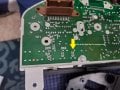
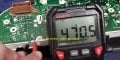
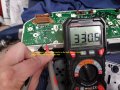
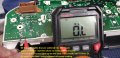
I have a light that doesn't come on on the dash. I'm not sure if it's necessary for the circuit. I've tried testing the other lights to get a baseline, but the results aren't what I expected, but I know very little about circuitry design, and I'm wondering if anyone can tell me based on my multimeter test if the light is indeed suspect.

I don't know if the light is necessary to complete the circuit for the alternator so that it wakes up, but it's been driving me nuts!

(In the circuit diagram on the service manual, it calls the light a "combination meter charge warning lamp", so it's been making me think that it's necessary to 'gauge' the circuit...but I'm shooting in the dark here!)

Can anyone tell me if the light on the dash is indeed burned out?

Any help will be appreciated! Thank you!
 

Attachments

MrChips

Joined Oct 2, 2009
34,628
In the good old days, all dashboard lamps would turn on before the engine starts. This is a check for burnt out lamps.

I don’t know how they do it today with all-digital systems.
 

Thread Starter

Random_name

Joined Aug 31, 2021
6
In the good old days, all dashboard lamps would turn on before the engine starts. This is a check for burnt out lamps.

I don’t know how they do it today with all-digital systems.
It's an old car - a 2002 Sentra - and all the lights come on except this one.
 

Thread Starter

Random_name

Joined Aug 31, 2021
6
The soldered in one that I tested? It's not a small job for me, so I'd like to make sure it's actually at fault before I search for a new solder-in bulb, etc.
 

Thread Starter

Random_name

Joined Aug 31, 2021
6
yes, that's the lamp that I'm trying to figure out. In the first pic, it looks like the light is essential to completing the circuit and powering up the alternator...or am I reading that wrong?

Do my readings make sense? What should resistance be for a properly functioning alternator warning light?
 

Thread Starter

Random_name

Joined Aug 31, 2021
6
I guess my main questions are: 1. is the light testing as 'ok' if it shows that many ohms?
2. Is the light wired in parallel with the circuit, or in series - i.e., is it essential for the light to come on for the alternator to 'wake up' and start working?

I'm not an electrician, so I'm just grasping at ideas!
 

MrChips

Joined Oct 2, 2009
34,628
Simple questions you can answer.

1) Does the car start?
2) Is the battery charging? The voltage across the battery should read about 14.5 V while the engine is running.
 

Thread Starter

Random_name

Joined Aug 31, 2021
6
Simple questions you can answer.

1) Does the car start?
2) Is the battery charging? The voltage across the battery should read about 14.5 V while the engine is running.
Yes, the car starts - no problem at all.
No, the battery is not charging. No voltage at all from the brand new alternator. No fuses blown, all connections tight. Figured this might be a cause - or it might be a defective alternator. THe issue is I don't know enough about multimeters and circuits to know what a functioning bulb should show!
 

MrChips

Joined Oct 2, 2009
34,628
Yes, the car starts - no problem at all.
No, the battery is not charging. No voltage at all from the brand new alternator. No fuses blown, all connections tight. Figured this might be a cause - or it might be a defective alternator. THe issue is I don't know enough about multimeters and circuits to know what a functioning bulb should show!
I don't know what type of bulb is being used. It is either an incandescent lamp or an LED.
In general, you cannot test the bulb while it is in-circuit. The other parts of the circuit will affect the meter reading.
Your only option, as far as I know, is to remove the bulb and test it. If that is going to be a lot of trouble, I would suggest getting a new bulb ready at hand.

Sorry, I only just noticed that you posted photos of the component side of the board. I assume that the bulb is on the reverse side.

There are some resistors labelled R214 and R211. I cannot make out the label on the third resistor. What are the numbers printed on the body of the resistors?

It looks like the bulbs on the reverse side are LEDs.
When measuring resistance with your meter, you need to take two readings. Take a reading one way. Then take a second reading with the RED and BLACK probes interchanged. Compare your readings for the bulbs showing on the bottom row.
If possible, do this in a dark room and see if the LED lights up while doing this test.
 

geekoftheweek

Joined Oct 6, 2013
1,429
Considering the diagram shows a diode labeled as a "charge warning lamp" my guess is the light is an LED. Usually if the bulb is replaceable it won't be soldered in place. Most everything produced in the last 20 years or so doesn't use actual lights and they aren't something that will cause the circuit to fail if they don't work like in the older days.

Personally I would test for voltage at the pin in the connector for that going in to the alternator (#2 shown in the diagram). It should probably be a couple volts less than battery voltage when disconnected from the alternator.

The fact that is is a new alternator and still not working makes me want to think you have a ground issue with pins 5 and 6 out of the alternator. That would also explain an indicator not working.
 
Top