Test winding in zero sequence current transformers

Thread Starter

Blue_Electronx

Joined Jun 10, 2019
112
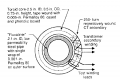
Sometimes it is common to see a zero sequence current transformer with four output wires, i.e., the secondary winding and the test winding as shown in the attachment. What kind of signal is the test signal? Is it like injecting a current signal that it is induced in the actual secondary? I want to perform this test with a microcontroller, so I wonder if I can connect this winding directly from the micro ports?

Source of the picture: T. Novak, L. A. Morley and F. C. Trutt, "Sensitive ground-fault relaying," in IEEE Transactions on Industry Applications, vol. 24, no. 5, pp. 853-861, Sept.-Oct. 1988.
 

Attachments

crutschow

Joined Mar 14, 2008
34,201
The winding could be used to input a small AC signal to test that the output signal winding is working.
But the signal must be AC with a zero DC average so, if you want to use a micro port, it would need to go through a series capacitor of appropriate size.
Note that the port must be placed in a high-impedance state when not testing, otherwise the normal current signal may be attenuated.

You'd have to look at the transformer specs to know what the input to output signal level would be.
You may need an amplifier at the port output to get a measurable signal.
 

Thread Starter

Blue_Electronx

Joined Jun 10, 2019
112
The winding could be used to input a small AC signal to test that the output signal winding is working.
But the signal must be AC with a zero DC average so, if you want to use a micro port, it would need to go through a series capacitor of appropriate size.
Note that the port must be placed in a high-impedance state when not testing, otherwise the normal current signal may be attenuated.

You'd have to look at the transformer specs to know what the input to output signal level would be.
You may need an amplifier at the port output to get a measurable signal.

My current transformer has 1000 turns secondary , and 1000 turns the test winding as well. Would the idea below work? The PWM with the low pass filter to get a sinusoidal voltage and the amplifier with the FET to get a 50 Hz sinusoidal current of about 20mA?


crutschow

Joined Mar 14, 2008
34,201
That circuit generates an average DC (unidirectional) current through the transformer which can saturate the transformer core.
That's I said the signal should be coupled through a capacitor to block any DC.
 

Thread Starter

Blue_Electronx

Joined Jun 10, 2019
112
That circuit generates an average DC (unidirectional) current through the transformer which can saturate the transformer core.
That's I said the signal should be coupled through a capacitor to block any DC.
Do you mean adding a coupling capacitor at the non-inverting input of the op amp (in the circuit above)?
 

crutschow

Joined Mar 14, 2008
34,201
Do you mean adding a coupling capacitor at the non-inverting input of the op amp (in the circuit above)?
No.
The signal to the transformer would still be unipolar with a DC component.
The capacitor has to be in series with the transformer winding.
That will mean a different form of the amp to drive the winding (such as a totem-pole or push-pull driver).
 

Thread Starter

Blue_Electronx

Joined Jun 10, 2019
112
No.
The signal to the transformer would still be unipolar with a DC component.
The capacitor has to be in series with the transformer winding.
That will mean a different form of the amp to drive the winding (such as a totem-pole or push-pull driver).
Do you know a reference documentation/schematic I can read on this?
 

Thread Starter

Blue_Electronx

Joined Jun 10, 2019
112
That should work if the op amp has sufficient current drive to give a detectable signal.
What I'm not clear is how much current I should give and the behavior of the test winding. Is this winding like a primary? Or is it another secondary that when you inject a current it induces in the other secondary? If both the secondary and the test windings are 1000 turns, then it makes sense they have a ratio of 1:1? I don't have much specs about this transformer, just the number of turns. It is used to detect currents above 15 mA in the one turn primary.
 

crutschow

Joined Mar 14, 2008
34,201
Is this winding like a primary?
Yes, it will act like a primary with the other winding being the secondary.
So, with the 1:1 ratio, the output current will be equal to the input current which, for your post #8 circuit, will be whatever the opamp maximum output current is, as determined by the winding resistance.
You may need to add a resistor in series with the op amp output.to limit the maximum current to whatever test current you want to see at the secondary.
 

Thread Starter

Blue_Electronx

Joined Jun 10, 2019
112
Yes, it will act like a primary with the other winding being the secondary.
So, with the 1:1 ratio, the output current will be equal to the input current which, for your post #8 circuit, will be whatever the opamp maximum output current is, as determined by the winding resistance.
You may need to add a resistor in series with the op amp output.to limit the maximum current to whatever test current you want to see at the secondary.
Let's say I have 30 mA in the actual primary. That means 30 mA/1000 = 30 uA in the secondary. So if the ratio between the test and secondary winding is 1:1, then I wouldn't have to output much current. If I inject 30 uA in the test winding, then I would see 30 uA in the secondary winding which is where the amplifier circuit is connected for the ADC. Am I right?
 

Thread Starter

Blue_Electronx

Joined Jun 10, 2019
112
One additional question. The circuit below then should work. I'll test it. As you said, I added R2 to limit the max current. The resistance of the test winding (measured with a meter) ranges across 75-100 ohms in different models. Doesn't R2 and C2 present a load for the test winding? Putting the micro port in high impedance would help? Also, as the ratio between secondary and test winding is 1:1, does the burden resistor across the actual secondary present a load for the test drive?


crutschow

Joined Mar 14, 2008
34,201
Doesn't R2 and C2 present a load for the test winding?
Yes.
This is a current transformer, so the voltage from the op amp is to generate a current, which is limited by R2 and the winding resistance.
This will generate a current through the burden resistor.
C2 should be large so it only blocks DC and has little effect on the AC signal.
Putting the micro port in high impedance would help?
I don't understand.
Wouldn't that stop the signal?
does the burden resistor across the actual secondary present a load for the test drive?
Yes.
Since it's likely a low resistance, it would add a resistance load in parallel about equal to the primary resistance.
You need to experimentally determine what signal are resistor values work best to give the desired output.
 
Last edited:

crutschow

Joined Mar 14, 2008
34,201
I need to isolate the test winding when no testing so it doesn't interfere with the secondary.
The op amp has a low output impedance, so the transformer would still see R2 as a load.
You could use a switch (mechanical, relay, or CMOS analog such as the CD4066) at the op amp output to totally isolate the winding when you are not testing.
 
Top