Test winding in zero sequence current transformers

Thread Starter

Blue_Electronx

Joined Jun 10, 2019
112
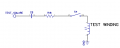
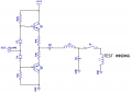
@crutschow Doing some research I found the circuit attached below. I was thinking that I only need 1 mA of test current so I may get away without the amplifier. What do you think of this circuit? C8 is the coupling cap, and L3 limits the current provided that it has higher impedance than the test winding. Note the LPF is not present at the amplifier input. Could I ensure the 1 mA/60Hz regardless of the load if I connect it directly from the micro port? And another question is, should I use a 60Hz square-wave or variably duty cycle pwm from the micro?
 

Attachments

crutschow

Joined Mar 14, 2008
34,201
should I use a 60Hz square-wave or variably duty cycle pwm from the micro?
A square-wave may be okay without any PWM
In that case you don't need the C9 and L3.
Just feed the square-wave directly into the winding and let the transformer do its thing
The output will likely be a somewhat grungy-looking square-wave, but that should be okay.
 

Thread Starter

Blue_Electronx

Joined Jun 10, 2019
112
A square-wave may be okay without any PWM
In that case you don't need the C9 and L3.
Just feed the square-wave directly into the winding and let the transformer do its thing
The output will likely be a somewhat grungy-looking square-wave, but that should be okay.
Something like this? In this case there's no LPF after the micro. Just the coupling cap, and R18 to limit the current. Maybe the test winding itself do the filtering? The square wave is 3.3V, so I have to size the components properly to get the current/frquency I want through the winding.
 

Attachments

Thread Starter

Blue_Electronx

Joined Jun 10, 2019
112
@crutschow One last question. As you saw in previous posts, I'm using an analog switch to open the test winding when no testing. Doesn't this cause a voltage across the test winding terminals? I'm not using a burden for it as I do for the secondary.
 

Thread Starter

Blue_Electronx

Joined Jun 10, 2019
112
It will cause a drop based upon the signal current through the analog switch's on-resistance.
I mean, when the switch is OFF and not current flows, the test winding is left open from the drive circuit. I'm confused because it's not good to leave a CT winding open since it develops a high voltage across it.
 

crutschow

Joined Mar 14, 2008
34,201
I'm confused because it's not good to leave a CT winding open since it develops a high voltage across it.
As long as the transformer output has the proper burden resistor connected to it, then the voltage from the measured current will remain low.
Remember that in a transformer, all the windings reflect the voltages in the other windings.
So if the output voltage is low, then the test winding voltage will also be low.
 

Thread Starter

Blue_Electronx

Joined Jun 10, 2019
112
As long as the transformer output has the proper burden resistor connected to it, then the voltage from the measured current will remain low.
Remember that in a transformer, all the windings reflect the voltages in the other windings.
So if the output voltage is low, then the test winding voltage will also be low.
One last question, the secondary has a DC offset of 1.65V. Would I need to reference the test winding to the DC offset as well, right? From what I understand, yes.
 
Top