Facebook
 Google
 GitHub
 Linkedin
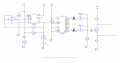
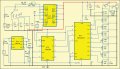
Can readers here please advise if there any design faults or ways to improve upon the attached circuit?
Will the CD4017 accept a 12V clock input directly from the LM555, so I can dispense with a 5V regulator?
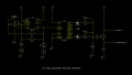
In terms of the generated waveform, how does "my design" compare with the 74HC4150 version also attached?
Thanks for any pointers.
Will the CD4017 accept a 12V clock input directly from the LM555, so I can dispense with a 5V regulator?
In terms of the generated waveform, how does "my design" compare with the 74HC4150 version also attached?
Thanks for any pointers.
Attachments
-
 17.1 KB Views: 48
 -
 214.7 KB Views: 41