It seems like it might be a challenge to properly wire a circuit if you can't even draw a simple schematic with COMPLETE information. Circuits can not wire themselves.
Has no-one mentioned DC PATH TO GROUND?
I bet that the inputs need a dc path to ground to bias them up. Value doesn’t matter too much so long as it is much bigger that the resistance of the load cell.
But mine behave like this: always output 4.4v as long as vdd = 5v and vee = 0v, no matter how and what the inputs are...
I was wondering if I have a wrong circuit... or some failed chips...
What are the voltage readings on the load cell signal + and signal - ? They should read the same and be half of of the supply voltage without any pressure on the cell.
It seems like it might be a challenge to properly wire a circuit if you can't even draw a simple schematic with COMPLETE information. Circuits can not wire themselves.
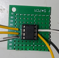
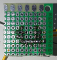
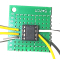
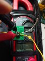
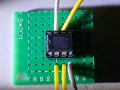
Here is the photos of my wiring and soldering. I have already checked **nothing is shorted accidentally**
Also, I have checked my load cell is functioning (0.0mv at rest, 2.0mv when I tried my best to bend it)
where
pin2: connected to load cell signal -ve
pin3: connected to load cell signal +ve
pin4: connected to load cell gnd
pin7: connected to load cell +ve
What are the voltage readings on the load cell signal + and signal - ? They should read the same and be half of of the supply voltage without any pressure on the cell.
the load cell signal + to ground = 2.48V
the load cell signal - to ground = 2.48V
signal+ to signal- = from 0.0mV to 2.0mV (i tried my best to bend the 20kg load cell)
other information:
V+ vs V- = 4.97V
VO vs REF = 4.43V
hi,
Do these wires have colours.?
pin2: connected to load cell signal -ve
pin3: connected to load cell signal +ve
pin4: connected to load cell gnd
pin7: connected to load cell +ve
EDIT.
I do not see any printed Coding on that IC.????
hi,
Do these wires have colours.?
pin2: connected to load cell signal -ve
pin3: connected to load cell signal +ve
pin4: connected to load cell gnd
pin7: connected to load cell +ve
Yes,
pin2 is the upper left yellow wire, connected to the load cell white wire
pin3 is the bottom left yellow wire, connected to the load cell green wire
pin4 is the grey wire, connected to the load cell black wire
pin7 is the white wire, connected to the load cell red wire
hi,
Do these wires have colours.?
pin2: connected to load cell signal -ve
pin3: connected to load cell signal +ve
pin4: connected to load cell gnd
pin7: connected to load cell +ve
Do you think my circuit is function? Should I try buying chips from other site / shop to replace the chip and see if it works? (p.s. I bought 3 INA122PA and they behave the same
Has no-one mentioned DC PATH TO GROUND?
I bet that the inputs need a dc path to ground to bias them up. Value doesn’t matter too much so long as it is much bigger that the resistance of the load cell.
I've been lurking. After only 13 posts, Ian nailed it in #14. The problem is the input from the load cell, specifically a ground or some other DC reference. Let's back up.
How many wires are there coming out of the load cell?
What are their colors?
What are their functions?
If the cell has connection points rather than wires, how many are there?
the red wire is power input, which could be from 5v to 10v according to the data from the dealer the black wire is ground, which should be connected to the negative terminal of the power source the green wire is signal +
the white wire is signal -
the load cell is functional, measured data is shown below:
the load cell signal + to ground = 2.48V
the load cell signal - to ground = 2.48V
signal+ to signal- = from 0.0mV to 2.0mV (i tried my best to bend the 20kg load cell)
V+ to V- = 4.97V
VO to REF = 4.43V
I was thinking the load cell is functioning correctly, but the chips or my circuit failed so that the voltage output is always 4.4V when input is 5V

 Facebook
 Google
 GitHub
 Linkedin