Template Code for dsPIC33EV 5V CAN-LIN Starter Kit

Thread Starter

Pedro_Lopes_951

Joined Mar 24, 2020
9
Hello everyone,
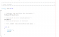
So I just started working for the first time with the dsPIC33EV 5V CAN-LIN Starter Kit(dsPIC33EV256GM106) and I was trying to write a simple code where I could switch on and off the LED'S on the board so that I could understand better how to work with the kit. After reading the reference manuals on the I/O PORTS and learning about the four registers (Tristx,PORTx,LATx,ODCx) I tried to use the demo code Microships has on their website rewriting it to try to get some LED's blinking but nothing happens. I am using the MPlabx IDE and the CX16 compiler. If someone has any demo code that is working that I could start I would be very thankful.
 

nsaspook

Joined Aug 27, 2009
13,265
In my just downloaded version of the demo code there are LED test routines.
http://ww1.microchip.com/downloads/en/DeviceDoc/DM330018_Starter_Kit_Demo.zip
C:
void LED_Receive(void)
{
    for (i = 0; i <= 5; i++) // fast blink all LEDs
    {
        LED1 = 0;
        LED2 = 0;
        LED3 = 0;
        delay_10ms(15);
        LED1 = 1;
        LED2 = 1;
        LED3 = 1;
        delay_10ms(12);
    }
}


void LED_Transmit(void)
{
    //
    // sequence LEDs on & off as a power-up test
    //
    LED1 = 1;
    LED2 = 0;
    LED3 = 0;
    //
    // wait 200ms, turn on LED2
    //
    delay_10ms(20);
    LED2 = 1;
    //
    // wait 200ms, turn on LED3
    //
    delay_10ms(20);
    LED3 = 1;
    //
    // wait 500ms, turn off LED3
    //
    delay_10ms(50);
    LED3 = 0;
    //
    // wait 200ms, turn off LED2
    //
    delay_10ms(20);
    LED2 = 0;
    //
    // wait 200ms, turn off LED1
    //
    delay_10ms(20);
    LED1 = 0;
}
main init code:
C:
int main(void)
{

    // Configure Oscillator Clock Source
    oscConfig();

    // Clear Interrupt Flags
    clearIntrflags();

    // Initialize hardware on the board
    init_hw();

    // Initialize the monitor UART2 module
    InitMonitor();

    // Test to see if we are in TRANSMIT or RECIEVE mode for the demo, show LEDs
    Test_Mode();

    if (mode == TRANSMIT)
    {
        LED_Transmit(); <<<<<<<<<<<<<<<<<<<<<<<<<<<<<<<<<<<<<<<<<<<<<<<<<<<<<<<<<<<<<<<<<<<<<<<<<<
    }
    else
    {
        LED_Receive();<<<<<<<<<<<<<<<<<<<<<<<<<<<<<<<<<<<<<<<<<<<<<<<<<<<<<<<<<<<<<<<<<<<<<<<<<<<<<<
        while ((SW1 == 0) | (SW2 == 0) | (SW3 == 0)); // wait to release all keys
        LED1 = 0; // initialize LEDs to all off
        LED2 = 0;
        LED3 = 0;
    }
    // Initialize the ADC converter
    ADCInit();

    // Initialize the modules for receive or transmit

    if (mode == TRANSMIT)
    {
        InitSENT1_TX();
        InitLIN_TX();
    }
    else
    {
        InitSENT1_RX();
        InitLIN_RX();
    }


    // Initialize the CAN module
        InitCAN();

    // main loop: every 4 Timer1 ticks (1sec), scan the sensors and transmit the data
    // or wait for a Receive interrupt from 1 of the 3 interfaces
    //
    s_tick = 0;
    while (1)
    {
        if (mode == RECEIVE)
        {
     /* check to see when a message is received and move the message
        into RAM and parse the message */
        if(canRxMessage.buffer_status == CAN_BUF_FULL)
        {
            rxECAN(&canRxMessage);

            /* reset the flag when done */
            canRxMessage.buffer_status = CAN_BUF_EMPTY;
        }
       
            Receive_Data();
            s_tick = 0;
        }
        else if (mode == TRANSMIT)
        {
 //
 // wait for the 250ms timer. User can accumulate s_ticks to get longer delays
 //
            while (s_tick <= 3);        // wait for 1 second
            s_tick = 0;                 // clear flag
            Transmit_Data();

        }
    }
}
A while loop after init_hw(); in main that contains one or more if the LED routines should work.
 
Top