Technics SX-PR603 Digital Piano

Thread Starter

emmet422

Joined Sep 1, 2024
58
pardon my naiveté…
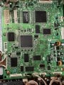
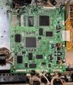
i have an old Technics piano -SX- PR603
and it stopped making sound after shipping. The digital performance seems ok, but the amplifier board seems only half powered - the 2 power transistors on the lhs (viewed from back of instrument) get warm, but the 4 on the upper right do not. I’ve cleaned /reseated connectors everywhere to no avail.
the red power light on the front near the headphone jack doesn’t come on, and there is no sound either through speakers or headphones.
the transformer supplies low voltages - about 5.4 to one if the inputs and 1.4 to the other.
i’ve ordered a service manual, but if there are any simple checks you can recommend, that will be much appreciated.
 

MrChips

Joined Oct 2, 2009
34,628
Welcome to AAC!

Technics SX PR603 Electric Piano Power and AMP Board 2.jpg

You start by examining the voltages on the power supply circuit.

Technics SX PR603 PSU circuit1.jpg
Technics SX PR603 PSU circuit2.jpg
Technics SX PR603 PSU circuit3.jpg

Look for +15 VDC and -15 VDC on the connectors shown above.
 

Thread Starter

emmet422

Joined Sep 1, 2024
58
(embarrassed smile) the +VCC and -VCC, yes?
those are + and -40v

i know that sounds ridiculous, and thank you for your willingness to help

and the picture you sent corresponds to the board i have
 

Attachments

MrChips

Joined Oct 2, 2009
34,628
Power transistors mounted on heatsinks are expected to get warn. That is why they are mounted on heatsinks in the first place.

If you measure +40 VDC at +VCC and -40 VDC at -VCC, that is a good sign.
Now try and see if you can measure + 15 VDC and -15 VDC where it shows +15A and -15A.
 

MrChips

Joined Oct 2, 2009
34,628
The next step is to do some signal tracing. If you do not have access to an oscilloscope, we have to resort to the next best approach. You will have to get your hands on a PC powered speaker. Even a bluetooth wireless speaker will do.
 

MrChips

Joined Oct 2, 2009
34,628
The photo you posted of the power supply board has great resolution.
Can you post a photo of the main processor board?
 

MrChips

Joined Oct 2, 2009
34,628
With an oscilloscope or amplified speaker, try to trace signal at CN202 pin-4 (ROUT) and pin-5 (LOUT) while playing a note on the piano keys (or in demo play mode).

When using an amplified speaker, use a 10 μF capacitor in series with the amplifier speaker as your input probe. The value of the capacitor is not critical. The purpose of the capacitor is to AC couple the signal thus preventing any DC from the speaker feeding back into your test points.

Technics SX-PR603 Main Board3.jpgTechnics SX PR603 DAC OUT.jpg
 

Thread Starter

emmet422

Joined Sep 1, 2024
58
any thoughts on oscilloscope settings?
doesn’t look good; with either demo or key presses, the left and right channels are just tens of mV noise- as is the nominal ground. i had to remove the connector to get access; am assuming it’s an output not an input.

i used 200mV/div and 250ms time base

scope is a lot fancier than i am used to. (though simple by today’s standards.)
 

Attachments

Last edited:

Thread Starter

emmet422

Joined Sep 1, 2024
58
Good news!
- a bit more fiddling with probe while in demo mode gave me this; i put the connector back in and was able to contact through side
 

Attachments

Last edited:

Thread Starter

emmet422

Joined Sep 1, 2024
58
Additional info:, on the analog board, q16,17,18,19 are stone cold.

a while ago, i tried feeding in a signal through the aux in but heard nothing
 
Last edited:

Thread Starter

emmet422

Joined Sep 1, 2024
58
sorry for all the separate posts…
I changed the volume settings on the control panel and the signal responded!
so despite my first try, it seems something is alive. I haven’t used the piano enough to be confident with the demo menus; i think a selection of sounds is necessary along with pushing the ’demo’ button
 
Last edited:

MrChips

Joined Oct 2, 2009
34,628
Tektronix TDS210 is a fine oscilloscope.

Check the markings on the probes and see if they are x1 or x10 attenuation. I prefer to use the probes on x10 attenuation.
Make sure the oscilloscope CH1 and CH2 inputs are set to match the probe's attenuation.

At this point, you can set the CH1 and CH2 inputs to AC unless I ask you to set it DC.
You just need to see that the waveform is symmetrical about 0V axis and give us an estimate of the peak-to-peak voltage.

Adjust the Horizontal SEC/DIV to give adequate waves on the screen, 100 ms - 1 ms should be fine.

Sounds like you are making some headway. I have to take a break before I can give you your next steps.
 

Thread Starter

emmet422

Joined Sep 1, 2024
58
Thank you so very much! I will be away for a few days, so the timing sounds fine. I will double check, but the last image convinced me there is a signal . I should receive the service manual next week, but your guidance is awesome. I’m not a EE, so have limited electronics experience.
 

Attachments

Top