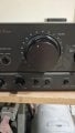
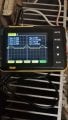
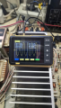
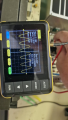
Technics SU VX-800 with blown components (another one)

Thread Starter

alprampo

Joined May 29, 2026
18
Good morning!

I set up a small test bench: I opened an online signal generator on my laptop and verified the output coming from the headphone jack first.
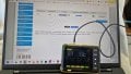
1788599711715.jpeg

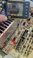
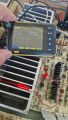
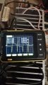
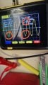
Then I connected the laptop to the amplifier and hooked up the scope to the speaker outputs. Here is what I found:
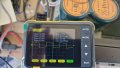
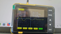
  • Left channel: The signal is heavily distorted and no longer a clean sine wave.
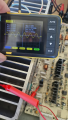
1788600104874.jpeg


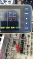
  • Right channel: The waveform keeps changing continuously (I captured a screenshot of this).
1788600279927.png

At this point, I've reached the limit of my expertise. In theory, I know I should trace the signal starting from the input, through the preamp section, and see where the waveform gets distorted, but I'm not sure which specific test points to probe on the schematic/board.

Any guidance on where to start tracing would be greatly appreciated!

Thanks,

Alberto
 

MrChips

Joined Oct 2, 2009
35,120
Good to see that you are learning to use the oscilloscope and that you have found a source for a sine wave.

Start with a test frequency of 1 kHz and focus on the LEFT channel.

It is important that you keep the amplitude of the input sine wave to a low level so that you do not overload the circuits.

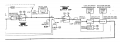
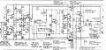
Follow the signal chain and look at the signal at strategic locations. Look at the BLOCK DIAGRAM to see the big picture and follow the CIRCUIT DIAGRAM for component details.

For example, start at the VOLUME control. Look at the actual component layout on the circuit board and select a test point that is easily accessible with least chance of creating a short circuit. If the signal is distorted there, work backward. If the signal is good, go forward.

1788613178406.png
 

Thread Starter

alprampo

Joined May 29, 2026
18
Good to see that you are learning to use the oscilloscope and that you have found a source for a sine wave.

Start with a test frequency of 1 kHz and focus on the LEFT channel.

It is important that you keep the amplitude of the input sine wave to a low level so that you do not overload the circuits.

Follow the signal chain and look at the signal at strategic locations. Look at the BLOCK DIAGRAM to see the big picture and follow the CIRCUIT DIAGRAM for component details.

For example, start at the VOLUME control. Look at the actual component layout on the circuit board and select a test point that is easily accessible with least chance of creating a short circuit. If the signal is distorted there, work backward. If the signal is good, go forward.
Thanks, that's a very clear explanation!

I would start by going backward using the Direct Input, which bypasses the tone control and the input selector. However, I’ve already tested all controls (Bass, Treble, Balance, and Loudness) and they clearly affect the audio signal, which suggests that section is working correctly.

My plan is to start measuring at the bases of power transistors Q507 and Q509, then work backward to the emitters and bases of Q503 and Q505.

Regarding the operational amplifier IC: I can see that the output is on pin 7, but where is the input? Looking at the schematic, my guess would be pin 5.

Thanks
Alberto
 

Pyrex

Joined Feb 16, 2022
540
Thanks, that's a very clear explanation!

I would start by going backward using the Direct Input, which bypasses the tone control and the input selector. However, I’ve already tested all controls (Bass, Treble, Balance, and Loudness) and they clearly affect the audio signal, which suggests that section is working correctly.

My plan is to start measuring at the bases of power transistors Q507 and Q509, then work backward to the emitters and bases of Q503 and Q505.

Regarding the operational amplifier IC: I can see that the output is on pin 7, but where is the input? Looking at the schematic, my guess would be pin 5.

Thanks
Alberto
the input is pin 5 , it's a noninverting input. Voltage on both inputs of IC401 is very small, you better check voltage on R453/R475
 

Thread Starter

alprampo

Joined May 29, 2026
18
the input is pin 5 , it's a noninverting input. Voltage on both inputs of IC401 is very small, you better check voltage on R453/R475
Thank you Pyrex for guiding me!

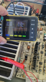
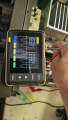
I injected a 1 kHz signal into the Direct Input and connected the scope between ground and the emitters/bases of both the driver and power transistors.

I noticed that once the speaker relay engages, the wave amplitude increases on almost all bases and emitters, except for the base of Q507. Also, on the base of Q509 with the speaker disconnected, the signal appears to be clean


1788707756189.jpeg
(And yes, I realized there’s a high risk of causing a short circuit with the alligator clips!) :)

with the speakers on:
1788707931011.png

Q505 base w/speaker off
1788708174135.png

Emitter with speaker off , does it seem to be not clean?:
1788708227105.png

Q503 emitter speaker off
1788708346309.png

here again but with speaker on
1788708397892.png

IC401 input (pin 5)
1788708572024.png
the output of IC401 is degraded, but tried 3 different without benefits.
Thanks
 

Thread Starter

alprampo

Joined May 29, 2026
18
Feed 1 kHz sine wave signal into the AUX input.
Probe TP401 L Channel +ve and -ve with the oscilloscope.

View attachment 371094
Sorry, I didn't see your message earlier. I will do this as soon as possible!

I can't test it right now because my wife has started complaining about what she considers a "huge waste of time"...


Regarding the other tests: even with a good input signal, the sound is weak and distorted on the left channel.

Why do the scope readings change as soon as a speaker is connected? This behavior starts right at pin 7 of IC401 and happens across all emitters and bases, except for the base of Q507.
Thanks!
Alberto
 

MrChips

Joined Oct 2, 2009
35,120
Your oscilloscope is showing peak-to-peak readings of 20 mV and 60 mV, etc.
That is way too low. What are the signals at TP401 and TP501 as you turn up the volume control?
 

Thread Starter

alprampo

Joined May 29, 2026
18
Your oscilloscope is showing peak-to-peak readings of 20 mV and 60 mV, etc.
That is way too low. What are the signals at TP401 and TP501 as you turn up the volume control?
This amplifier has always been hard to drive—the usual 700 mV input was never enough to drive it fully, and the volume pot is linear instead of logarithmic.

That said, when it was still working, I tested it per the service manual and measured correct 30 V AC at the speaker output with a given signal and knob turned fully clockwise.

Now, with the laptop output set to maximum, and knob as in picture, here are the readings at TP401
WhatsApp Image 2026-09-07 at 21.54.15.jpeg
WhatsApp Image 2026-09-07 at 21.55.30.jpeg


and TP501.
WhatsApp Image 2026-09-07 at 21.54.51.jpeg
Thanks a lot for your time!

Alberto
 

Thread Starter

alprampo

Joined May 29, 2026
18
Assuming you are referring to all the Q4xx and R4xx D4XX components, I will work on that section and let you know.
1788814180898.png
Is it okay to inspect this area using a 1 kHz sine wave signal and the oscilloscope for the transistor and tester for resistors (with power off)
?

Thanks,

Alberto

 

MrChips

Joined Oct 2, 2009
35,120
No. At this stage, the objective is to trace the signal on the live circuit.
Inject 1 kHz sine wave at the AUX input and follow where in the signal chain the signal is good and not good.

You can start anywhere and work your way forward and backward until you find the trouble spot. It is like a traffic helicopter trying to pinpoint the exact place of the collision on the highway (but in the opposite sense, in one section of the highway, traffic is flowing smoothly but is stopped in another section).
 

Thread Starter

alprampo

Joined May 29, 2026
18
Thanks for the clear explanation, that helicopter analogy makes total sense!

Just a quick heads-up: I haven't disappeared from the thread, but I had to temporarily pause the testing. I noticed some humidity / moisture buildup on the transformers, so I need to let everything dry out completely before powering the unit back up.

Also, between work and family, my spare time is quite limited right now, so progress might be a bit slow—I really hope you guys won't give up on me!

I'll update the thread as soon as I can safely resume signal tracing.

Thanks
Alberto
 

Thread Starter

alprampo

Joined May 29, 2026
18
Dear guys,

I finally found some spare time to set up a safer environment to perform the tests!

I tested the amplifier without the series lamp (direct mains power) under the following conditions:

  • Input: AUX channel, laptop feeding a 150 mV / 1 kHz sine wave
  • Settings: Volume knob set to 50%, speakers turned OFF
I checked the signal coming from the volume board on CN302A, and it looks clean on both channels.

Next, I probed Q427 and Q429:

  • The signal appears clean on the emitters.
  • On the bases, the crests (peaks) of the waveform look slightly distorted/clipped.


1789502201573.jpeg

Then I checked the emitters and bases on the following transistors:

  • Q423 & Q425: Clean waveform.
  • Q413 & Q415: Clean waveform.
  • Q409 & Q411: Flat signal (DC level). I assume these are part of the power supply/bias circuit rather than the signal path. The same goes for Q403 & Q401.
  • Q405 & Q407: OK (clean waveform).
  • Q421 & Q419: Good waveform.
  • Q503 & Q505: Also showing a good waveform.
However, things change completely once the speakers are turned ON:


1789503164176.png
1789503258514.png

With speakers turned ON:

The peak-to-peak voltage shown on the scope increases significantly, and the waveform gets heavily distorted on Q507, Q509, Q503, and Q505, as well as on pin 7 of IC401 (while pins 5 and 6 remain clean).

I also tried pulling IC401 out to test without it, but the behavior remains exactly the same.

For comparison, here is how it looks with speakers OFF:


1789503209457.png


I'm starting to go a bit crazy with this one—my technical knowledge is reaching its limits and I'm feeling stuck. I really can't figure out why everything looks clean until a load is applied.

Does anyone have a suggestion on what I should check next, or how to isolate whether this is a power supply issue under load, a bias/current limiting problem, or something in the feedback loop?

Any guidance or step-by-step advice would be hugely appreciated!
Thanks
Alberto
 

MrChips

Joined Oct 2, 2009
35,120
As I said before, the squiggles in the waveform are the results of the low resolution of your oscilloscope. Ignore these.

With the speakers turned on, you are measuring overload distortion at 21V peak-to-peak. Those voltages are large. Turn the volume down. I have not checked what signals you are testing.
Is the sound from the speakers adequate and not distorted?
 

MrChips

Joined Oct 2, 2009
35,120
I looked to see what you are testing.
This is a directly coupled amplifier with feedback. You cannot pull IC401.

As I said, turn the volume down and look at the signals at TP501. I am assuming that you have Q507 and Q509 installed.
 
Top