TDA2030 current drop

Thread Starter

tmarco

Joined May 31, 2018
22
Hi guys,

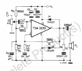
I have recently obtained a TDA2030 amplifier module ( https://www.ebay.com/itm/TDA2030A-A...-Amplifier-Board-AMP-6-12V-1-18W/192163691131 ) and am trying to test its performance against the specs. The load is a 4.5 Ohm 20W power resistor, the power supply is a
Basetech 150W (30V, 5A) SMPS, and im using a signal generator (50 Ohm output impedance) to drive it. I'm using an oscilloscope to measure the
RMS voltage across the load, and compute the power as Vl^2 / Rload . The problem is that when I compare my results to the specs it seems that
my module is delivering a significantly lower power than expected. Here is an example measurement:

F: 20 kHz 100 kHz
Vs: 12 V 12 V
Is: 0.27 A 0.29 A
Vl: 2.5 V 2.1 V
Pl: 1.4 W 1 W

In both cases the signal is a clean sine wave, there is no clipping or distortion. According to the specs, the power bandwidth for a 4 Ohm load is 15W up to 100 kHz. For the same load resistance, the datasheet gives the supply voltage required to achieve 15W as 12V. So something is obviously wrong, either with my measurements or with the amplifier module. If someone has an idea what could be going wrong, or any suggestions on narrowing down the source of the error I'd be very happy to hear about it.

cheers,
T
 
Last edited by a moderator:

recklessrog

Joined May 23, 2013
985
Before you get too deeply into it, are you using a x10 probe and taken this into account when viewing on the 'scope? how are you measuring the current? it is low for an output of 15W. and more in line with your low output level. Take a look at the attached data file for the ic, it shows it needs a positive and negative supply. How does the module you have schematic compare to the one in the data sheet?
Try increasing the drive to the onset of output clipping, then see what power you are getting.
 

Attachments

Last edited:

DECELL

Joined Apr 23, 2018
96
Mmm. 10x. Could be
I last used one of these in 1982- they're a real fossil. This is from STs datasheet. Power Specd at +/- 19V!

upload_2018-5-31_16-55-31.png
Are you sure about the power?upload_2018-5-31_16-52-28.png
 

Thread Starter

tmarco

Joined May 31, 2018
22
Yes, I'm using a 10x probe with the correct setting on the scope. I'm not measuring the load current, only the load voltage. (Is) is the current
from the SMPS into the TDA module. I am not sure about RMS/peak music power, but I assumed it would be RMS. I can't find a clarification in the datasheet ( https://www.rapidonline.com/pdf/82-0630.pdf ). Another thing that happens is that when I increase the input voltage from the signal generator (and the power supply voltage accordingly, otherwise the output starts clipping) then I manage to get to a load voltage of about 7 Vrms, which sources about 1.4 amps from the SMPS into the TDA module, and this corresponds to about 11 Watts output power. But then suddenly the current starts dropping and goes to about 0.3 or 0.4 amps and settles there. It is as if I would be crossing some threshold just as I'm reaching sensible power levels. Could it be that the module itself is somehow limited? On the ebay product page it says it can put out 18W with a supply of 12V, but I'm not sure how accurate that is.
 

DECELL

Joined Apr 23, 2018
96
Power Specd at +/-19V (38V) in your datasheet too. 12V is the minimum supply voltage for a 2030. The ebay page is lying!
 

Thread Starter

tmarco

Joined May 31, 2018
22
I just checked everything again (probe, coupling, acquisition mode, connections) and did another measurement. At F = 20 kHz with the PSU set to 30V and a signal drive voltage of 0.7V (max before clipping), the current into the TDA module is 0.85A. I get to about 7.5 Vrms across the load. This corresponds to 12.5 W output power, which is already significantly closer to the specs. But the problem is that this holds for maybe 30 seconds and then the signals suddenly starts distorting/fading and becoming messy. This is accompanied by a current drop to ~0.25 A. Then if I shut off the power supply and drive signal, leave it for a short while (5 seconds), and then re-start it, the same thing happens. I have attached two screenshots from the scope, the first one is with ~7.5 Vrms across the load (Vk), and the other one shows the start of distortion, just before it becomes completely incoherent (partial peaks, etc). Thanks for helping me out guys.wav1.jpg wav2.jpg
 

recklessrog

Joined May 23, 2013
985
[QUOTE="tmarco, post: On the ebay product page it says it can put out 18W with a supply of 12V, but I'm not sure how accurate that is.[/QUOTE]

Does your module require a positive and negative supply? ie +12 & -12 volts. (24 volts total) The efficiency will not be 100%, so just because it draws say 10 Watts, does not mean you will get 10Watts output, more likely to be around 5, maybe 8 watts. Take a look at the graph from DECELL above, look at the supply voltage for 10 watts.
The i.c does have an internal overload protection circuit built in so this could be why it shuts down. I'm very suspicious about getting 15 w out of that device at only 12V.
The crossover distortion could very well be caused by insufficient or wrong supply. The spec sheet show a min +6 and -6 volt supply, and at that you may get a few watts, but it needs +22 and -22volts for 20 watts output. Think of two twelve volt batteries in series, the junction is 0 volts, and with respect to 0 volts you have +12 and -12 volts to power the ic from a dual supply. Then you may well get your expected 15 or so watts output.
 
Last edited:

Thread Starter

tmarco

Joined May 31, 2018
22
Ok guys, I'm really sorry for this, but I think I know what the problem is. It seems that my load resistor is after all not able to handle 20W, but a

significantly lower power ( I don't know exactly now). I had it from a scrapbox and I think i mistook the value (it has a serial no but it is an old

resistor and I couldnt find online information

about the power rating). So now that I have increased the power supply to 30V (the ebay page is completely misleading) and scaled the input

signal to max before clipping, I'm getting 12.5 Watts on the 4.5 Ohm load (for my application I only need 5 Watts so this is more than sufficient).

But I think because the load is not designed for this power something

happens to the resistance when it gets too hot and therefore the signal fades/distorts and current drops. Is this possible? There is no

damage to the resistor or anything like it, but it seems that the less time i give it to cool down, the less time it takes after startup for it to \

distort/fade again. And the load resistance after powering it is still the same, so there are no permanent changes to the resistance.

PS: I have checked and it looks like the TDA can be run both with dual and single rail supplies. So I think that the values I'm measuring are quite in line with the specs, aside from the distortion/fading which sets on after 40-50 seconds of operation when resistors are at room temperature.
 
Last edited:

recklessrog

Joined May 23, 2013
985
Sounds more like the inbuilt protection kicking in, it has thermal shutdown too.
Remember that there is a big difference in the heat dissipation from the chip when fed with audio. Although it may well reach 15 W on peaks, the average will be much lower so it does not run too hot. With continuous sinewave drive, you are pushing the thermal capabilities to the limit when working at max output. If the heatsink can't get rid of the heat quickly enough, the thermal protection will cut in until it has cooled again.
 
Last edited:

Thread Starter

tmarco

Joined May 31, 2018
22
Ok, so what does that mean? It should be rated for the given supply voltage/power. Is the heatsink insufficient? Maybe I should contact

the seller and request a schematic.
 

recklessrog

Joined May 23, 2013
985
It depends on what you are using it for, If it is as an audio (voice, music) amplifier driving a loudspeaker, you will probably be ok as the average dissipation will be within tolerable limits. Also the impedance of the speaker is nominal and will be higher a high frequencies.
If on the other hand, you want to feed a fixed frequency into a purely resistive load, you may have to either de-rate your power requirement by at least 50% or fit a fan to cool the heatsink or both.
 

Thread Starter

tmarco

Joined May 31, 2018
22
Ok, I think I understand. I will actually only be needing 5W max, so I think I will de-rate the power req and see

whether it can run continuously, if not then I guess I will use a fan to cool it. Thanks recklessrog (and others), you've been a real help.

cheers
 

recklessrog

Joined May 23, 2013
985
Ok, I think I understand. I will actually only be needing 5W max, so I think I will de-rate the power req and see

whether it can run continuously, if not then I guess I will use a fan to cool it. Thanks recklessrog (and others), you've been a real help.

cheers
You are welcome, Keep us posted as to how you get on :)
Oh sorry, just spotted that you joined today, Greetings and welcome :) :)
 

Audioguru

Joined Dec 20, 2007
11,248
ebay and its seller know nothing about electronics. They do not know how to read the datasheet for a TDA2030 IC (translation problem?) and they use a heatsink that is much too small.
 

Thread Starter

tmarco

Joined May 31, 2018
22
Yes, I think I have come to the same conclusion. I have some spare heatsinks lying around so I'll also look into

modifying the module that way.
 

Audioguru

Joined Dec 20, 2007
11,248
The LM1875 is still made by Texas Instruments and is almost the same as the obsolete TDA2030. Which one came first?
5W without any clipping into 4.5 ohms would need a power supply that is 18V to 20V.
 

Thread Starter

tmarco

Joined May 31, 2018
22
@Audioguru I don't think it's the original IC, seems like a chinese version / more recent production.

@DECELL you were right from the start, I just made the mistake of not taking the datasheet as my guidance instead of
the online info written by the seller. Learned my lesson. I will be using the TDA module to drive a higher power LW
amplifier for the 137kHz band. I used a small 1:3 impedance transformer to test the TDA on a 250W 50 Ohm dummy
load (Zin of the amp will also be 50), and I get 5.6 Watts at Vss = 17V and Vin = 1.1V (at 100kHz), so this is more or less
in line with what is spec'd in the datasheet, and satisfies my requirements.
 
Top