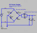
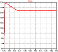
Many thanks for the sim test! Apart from the start-up that looks good. It would be interesting to know what would happen if you tuned that tank circuit to resonance. At 50hz and 50mH the cap should be around 202uF for a tuned circuit. Theoretically current draw from the AC source would drop as the impedance of the tank circuit approaches infinity. The idea is that this tank circuit could throttle the current so that no sharp spikes are seen from the big cap charging. I can see me wanting to adapt this for a 240v 50hz AC input with a 60vdc output for a some 30w LEDs I'm using to grow plants.
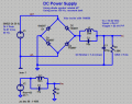
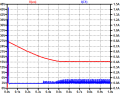
Here is the rerun with your values. You can make the ripple smaller, but at the expense of output voltage range. The relevant frequency of the ripple is 100 Hz. At that frequency:
\[ 2\pi fL\;=\;(2)(\pi)(100)(50\times 10^{-3})\;\approx\;31.4159\; \Omega \]
\[ (2\pi fC)^{-1}\;=\;((2)(\pi)(100)(202\times10^{-6})^{-1}\;\approx\;7.8790\;\Omega \]
they are not the same impedance so no resonant tank circuit here. In order for the parallel combination to be resonant at a frequency, the impedances must be equal at that frequency. Try again.
Thank you.
My values were based on the inductor being 50 milli henry. Does the 'm' in your circuit mean micro? To calculate the values for resonance at 50hz I used the calculator at http://www.1728.org/resfreq.htm
Please don't get the impression I understand what I'm talking about. I have no formal training and I only tinker occasionally.
Thank you.
My values were based on the inductor being 50 milli henry. Does the 'm' in your circuit mean micro? To calculate the values for resonance at 50hz I used the calculator at http://www.1728.org/resfreq.htm
Please don't get the impression I understand what I'm talking about. I have no formal training and I only tinker occasionally.
m is for milli or \( 10^{-3} \)
u or μ is for micro or \( 10^{-6} \)
n is for nano or \( 10^{-9} \)
p is for pico or \( 10^{-12} \)
Go back to post #23 and note the value I used for the inductor. Online calculators are a great convenience but it helps to double check. You can find solutions of LC pairs that are resonant at a given frequency, but the solutions are not unique. Why is that the case? It is because you have two unknowns, the L and the C, but there is only one equation which says the impedance of the L and the impedance of the C must be equal.
In simple arithmetic, if I ask for two numbers that equal 12 I can think of at leas three off the top of my head. The integer solutions are 3 x 4 and 6 x 2. If we are not restricted to integers the square root of 12 comes to mind. That's not the end of it however because there are a countable infinity of other solutions.
They both compute to 31.4 Ω. So I'll try those values later this afternoon. I still think you are going to have that nasty turn on problem where the output goes 7V above the expected value of 20 or so. The AC analysis of just the L & C shows a strong notch at 100 Hz. as we intended. There is definitely an insertion loss which is to be expected. The startup current in C1 is limited to 1.4 A, also as intended. The more I think about it the less I am inclined to believe that the resonance of the L&C has anything to do with what is actually going on. there are two reasons:
Capacitors C1 & C2 are in series and form a capacitive voltage divider. The total capacitance of series capacitors will be less than either of them, so it looks like less of a dead short at turn on.
Capacitors C1 & C2 are in series and form a capacitive voltage divider. The total capacitance of series capacitors will be less than either of them, so it looks like less of a dead short at turn on.
Regardless of anything you do in the circuit, the filter capacitor will always look like a dead short for a short time after turn on when there is no voltage across it. This is a function of the total capacitance. More capacitance is useful for reducing the ripple, but increases the magnitude of the initial current. People don'r realize that capacitors in series will have an effective capacitance that is the less than either individual value. The same is true for resistors and inductors in parallel. Check it out.
Regardless of anything you do in the circuit, the filter capacitor will always look like a dead short for a short time after turn on when there is no voltage across it. This is a function of the total capacitance. More capacitance is useful for reducing the ripple, but increases the magnitude of the initial current. People don'r realize that capacitors in series will have an effective capacitance that is the less than either individual value. The same is true for resistors and inductors in parallel. Check it out.
Forgive me for jumping in without studying the thread carefully, so this may or may not make sense here, but if you need to limit the initial turn-on current then in some cases an ICL (inrush current limiter) can help. It has an initial high resistance (relatively) that goes down as current runs through it.
Forgive me for jumping in without studying the thread carefully, so this may or may not make sense here, but if you need to limit the initial turn-on current then in some cases an ICL (inrush current limiter) can help. It has an initial high resistance (relatively) that goes down as current runs through it.

 Facebook
 Google
 GitHub
 Linkedin