Facebook
 Google
 GitHub
 Linkedin
Salutations,
I'm looking for assistance in troubleshooting my first circuit board based project.
Project Goal:
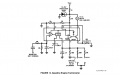
The tachometer was completely unresponsive in my old pickup truck. I would like to retain the look of the original instrumentation and took to find some sample circuits as a basis to begin. The truck has a 4 cylinder engine and the ignition is electronic with a General Motors type High-Energy-Ignition (HEI) trigger. I found a sample circuit in a booklet from Texas Instruments for a Gasoline Engine Tachometer which calls for IC LM2917. Please see attached image for the sample circuit, 'TI-Tach Schematic'.
The Bill of Materials I've used is as follows:
1. Zener Diode 20V 1.3W DO41 (Quantity 1) BZX85B20-TAPGICT-ND
2. Trimmer 500ohm 0.5W PC (Quantity 1) 3386P-501LF-ND
3. IC Converter Fq to Hz 14DIP (Quantity 1) LM2917N/NOPB-ND
4. Res 10ohm 0.5W 1% (Quantity 1) BC4399CT-ND
5. Res 470ohm 0.5W 1% (Quantity 1) BC4173CT-ND
6. Res 10kohm 0.5W 1% (Quantity 3) BC4393CT-ND
7. Res 20kohm 0.5W 1% (Quantity 1) BC4405CT-ND
8. Res 100kohm 0.5W 1% (Quantity 1) BC4394CT-ND
9. Cap 0.022uF Radial (Quantity 2) 399-4398-ND
10. Cap 1uF Axial (Quantity 1) 399-13735-1-ND
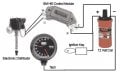
Everything soldered together quite nicely. I have verified that supply voltage to the tachometer is 12volts (~14v when engine is running) and the ground is OK. The signal wire is connected to the negative terminal of the ignition coil. The tachometer needle will respond when battery voltage is supplied, but the tachometer will not respond to any engine RPM variations or display any engine RPM signal whatsoever. I did experiment with the variable resistor (500ohm Trimmer) and the tachometer needle's resting point will change accordingly when supply voltage is applied.
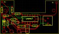
To see my circuit's layout on my PCB, please see the below attachment, 'Tach PCB Schematic'. I've followed continuity from component to component and cannot find anything obvious that may be preventing the tachometer from operating. If anyone can volunteer any advice or share their experience I would sincerely appreciate your contribution. Thank you for your time!
I'm looking for assistance in troubleshooting my first circuit board based project.
Project Goal:
The tachometer was completely unresponsive in my old pickup truck. I would like to retain the look of the original instrumentation and took to find some sample circuits as a basis to begin. The truck has a 4 cylinder engine and the ignition is electronic with a General Motors type High-Energy-Ignition (HEI) trigger. I found a sample circuit in a booklet from Texas Instruments for a Gasoline Engine Tachometer which calls for IC LM2917. Please see attached image for the sample circuit, 'TI-Tach Schematic'.
The Bill of Materials I've used is as follows:
1. Zener Diode 20V 1.3W DO41 (Quantity 1) BZX85B20-TAPGICT-ND
2. Trimmer 500ohm 0.5W PC (Quantity 1) 3386P-501LF-ND
3. IC Converter Fq to Hz 14DIP (Quantity 1) LM2917N/NOPB-ND
4. Res 10ohm 0.5W 1% (Quantity 1) BC4399CT-ND
5. Res 470ohm 0.5W 1% (Quantity 1) BC4173CT-ND
6. Res 10kohm 0.5W 1% (Quantity 3) BC4393CT-ND
7. Res 20kohm 0.5W 1% (Quantity 1) BC4405CT-ND
8. Res 100kohm 0.5W 1% (Quantity 1) BC4394CT-ND
9. Cap 0.022uF Radial (Quantity 2) 399-4398-ND
10. Cap 1uF Axial (Quantity 1) 399-13735-1-ND
Everything soldered together quite nicely. I have verified that supply voltage to the tachometer is 12volts (~14v when engine is running) and the ground is OK. The signal wire is connected to the negative terminal of the ignition coil. The tachometer needle will respond when battery voltage is supplied, but the tachometer will not respond to any engine RPM variations or display any engine RPM signal whatsoever. I did experiment with the variable resistor (500ohm Trimmer) and the tachometer needle's resting point will change accordingly when supply voltage is applied.
To see my circuit's layout on my PCB, please see the below attachment, 'Tach PCB Schematic'. I've followed continuity from component to component and cannot find anything obvious that may be preventing the tachometer from operating. If anyone can volunteer any advice or share their experience I would sincerely appreciate your contribution. Thank you for your time!
Attachments
-
 55.5 KB Views: 93
 -
 178.3 KB Views: 76