Sziklai Pair Amp not amping...

Thread Starter

SamR

Joined Mar 19, 2019
5,513
You do not need a pot to adjust the base voltage to be +3.6V. Instead you need two resistors as a voltage divider and some simple arithmetic since the base current of the first transistor is so low.
Since each transistor (even in the same batch) reacts differently the module allows me to "tune" the resistance for the best possible transistor amplification output. Then I can measure the resistance on each side of the wiper to match my bias resistor values to. Even calculating for the bias resistance output voltage is based on the specified transistor values and not what the individual transistor reacts to. The module is simply a shortcut method based on each individual transistor's reaction. At least that is the idea...
 

crutschow

Joined Mar 14, 2008
38,617
Even calculating for the bias resistance output voltage is based on the specified transistor values and not what the individual transistor reacts to.
True, but you need to look at the circuit sensitivity to the various transistor parameters.
The only transistor parameter of significance here in biasing the amp, is the variation in base-emitter voltage between transistors, and that is likely to be no more than a few tens of millivolts, so the calculated value will get you very close (likely within 100mV) to the desired value in the real circuit.
 

Thread Starter

SamR

Joined Mar 19, 2019
5,513
Mine can deliver +/-200 mA
I just reviewed my Siglent Specification Sheet and found no direct reference to output current rating. All I found was a 50W Max rating for the entire unit. I'm sure there would be a method of measuring the output current. Voltage across resistance? It does max at 20Vpp so +/- 10V which is pretty standard.
 

Thread Starter

SamR

Joined Mar 19, 2019
5,513
Well, 10V/50Ω gives me 200ma but not sure as to continuous vs. duty cycle. So it should be capable of instantaneous 200ma at least. Reading the specs, it says it is capable of DC out. Not that with all my other DC power supplies I'd probably ever want to use it but curious as to how it would be set up. I see nothing but the standard waveforms and sweeps and modulations and I believe white and pink noise functions. Setting the offset and phase for waveforms is simple but DC??? I assume they are referring to DC offset?
 

AnalogKid

Joined Aug 1, 2013
12,217
I just reviewed my Siglent Specification Sheet and found no direct reference to output current rating. All I found was a 50W Max rating for the entire unit. I'm sure there would be a method of measuring the output current. Voltage across resistance? It does max at 20Vpp so +/- 10V which is pretty standard.
Page 8 of the datasheet, DC Characteristics:

+/-10 V into a hi-Z load

+/-5 V into 50 ohms.

ak
 

crutschow

Joined Mar 14, 2008
38,617
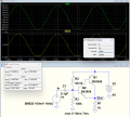
Just for grins, below is the LTspice simulation of the circuit:
I calculated the bias resistors R2 and R3 to generate 3.6V to give a 3V average output, assuming a base-emitter voltage of 0.6V for the low assumed Q2 base current.
The simulated average output voltage (Waveform window) shows 3.028V, only 28mV above my target value.
The AC output (small left window) is 197.7mVpp for a 200mVpp input, giving a gain of 0.988.

1691122291618.png
 

Thread Starter

SamR

Joined Mar 19, 2019
5,513
I still have a lot of book work to do on transistors but I also try and reinforce it with some actual circuit building and troubleshooting. I kinda missed the obvious on this one... Thanks for the input guys! Edit: I also need to work on my modeling in LTS as I got lazy on this one.
 

AnalogKid

Joined Aug 1, 2013
12,217
I also need to work on my modeling in LTS
Don't worry about it. I gave up on trying to keep up with Wally years ago.

Actually, it's working out nicely for me. In response to a question, I describe a circuit solution and then go for a bike ride. When I come back, sghioto has drawn a schematic and Wally has done a simulation.

Sweet.

ak
 
Last edited:
Top