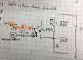
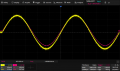
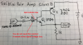
How do you expect to turn on Q1 with no DC base bias or path for DC (unidirectional) current?nput looks fine on the scope but only noise on the output. What have I missed here?
Yes, it rather acts like a Darlington since it has a high gain, but has only one base-emitter drop instead of two.it will have a voltage gain of only 1 (like an emitter follower).
Yes, an emitter follower gain is actually always slightly less than 1.It actually lost a few millivolts...
Don't understand this. Please explain.set the offset to 3.6 V. The circuit output should be centered around 3.0 V.
![IMG_1221[1].JPG IMG_1221[1].JPG](https://forum.allaboutcircuits.com/data/attachments/287/287434-d70485adbd34d66e8fb5faeb0fba9294.jpg)
Wow, this I did not know. Neat trick! There is very little information on using test instruments out there other than taking the basic measurements. Thanks! I have tried using it as a low voltage 60Hz AC source and found it pretty useless as it has almost no current. I'll have to do some experimenting with the DC offset. Yeah, DC offset won't work through the coupling capacitor. The 1k resistor was on the diagram I was working with but I eliminated it when I put my biasing module on the base although I did keep the coupling cap when I inputted the 1kHz signal from the sig gen. What I did notice was there was a very wide range of resistance values using my bias module that gave a perfect wave output. Which is very unusual as it typically is a very narrow range of tweaking the pot to get the correct output.If your function generator has the ability to add an adjustable DC offset to the sine wave output, then the function generator can supply the 3 Vdc by adding it to the sine wave as a constant offset voltage from GND. Now, as you turn the sine amplitude up and down, the DC voltage at the base will sti at 3 V. Note that for this to work, delete the 0.1 uF input coupling capacitor. Also, since your circuit is basically an emitter follower, you can delete the 1 K input resistor. The FG is supplying the DC bias voltage for the circuit to function correctly.
Correct. If the DC bias voltage is supplied externally, you don't want the output stage of the signal generator to fight it with its own output DC level, which probably is 0 V.I did keep the coupling cap when I inputted the 1kHz signal from the sig gen.
There are tons of low-cost function generators on amazon and ebay. One of the things that sets them apart from more expensive "professional" models is the analog signal output amplifier. Mine can deliver +/-200 mA while maintaining a very clean triangle/sawtooth wave, especially around the zero-crossing, plus no little artifacts at the peaks.I have tried using it as a low voltage 60Hz AC source and found it pretty useless as it has almost no current.
| Thread starter | Similar threads | Forum | Replies | Date |
|---|---|---|---|---|
| D | Sziklai Pair Push Pull Bias Question | General Electronics Chat | 12 | |
|
|
Push-Pull Amplifier and Sziklai Pair Questions | General Electronics Chat | 26 | |
| E | Sziklai pair design | General Electronics Chat | 13 | |
| S | Is it a Sziklai Pair? | Analog & Mixed-Signal Design | 8 | |
| T | PNP transistor (Sziklai) question | Homework Help | 1 |