Switching polarity of a DCC signal (model railway control)

crutschow

Joined Mar 14, 2008
38,913
I’ve tried explaining why it’s not as simple as you seem to think it is but get accused of bringing up straw man arguments.
Your accused, because many of your objections are.
And I've explained why it's not a complex as you seem to think it is,
I believe I've answered all your other straw-man objections.
One track sensor is available commercially for $15-$20.
Yes, there are expensive track sensors, and naturally your example uses the most expensive, but the TS wanted cheap and that's what I am proposing.

Inexpensive, small reed switches laid below the track (which can be covered by a thin layer of ballasting to hide them) along with a strong magnet glued to the bottom of the engine are being used (as in the YouTube video below).
It's simple and requires no additional circuitry to interface to my circuit.

So, for a one-way loop, it requires a magnet per locomotive, two reed switches, one cheap IC, and a DPDT relay with a one-transistor driver.
For a two-way loop it requires two more reed switches and an additional cheap IC.

Perhaps that seems too crude for your model railroader sensibilities, and it hasn't been designed by one of your model railroader EE's, but it's a valid option for a low cost sensor and controller for a reversing loop.

It the TS doesn't want to use it, I'm fine with that, but let's hear from him before you continue in you dogged attempts to pour cold water on the concept.
1714601264892.png
 

crutschow

Joined Mar 14, 2008
38,913
Except that assumes the trains will only go one direction round the loop, but they need to be able to move both ways.
Sigh. no.
I guess you still don't understand my post--

Below is the logic for trains from either direction with 4 sensors:
For just one direction and two sensors, the OR gates are not needed


1714519721258.png

The are four sensors, one at each entrance to the isolated loop , and one at each exit of the isolated loop.
Connected to the circuit above, as shown, it will correctly set the polarity no matter which way the train is moving.

Obviously this must appear to be more complicated than it is.
 
Last edited:

Thread Starter

AlbertHall

Joined Jun 4, 2014
12,660
I guess you still don't understand my post--
For a dual direction loop your system requires 4 sensors and two ICs.
For the system I linked to earlier it would require two sensors and one small PIC.
The sensors are like the link below which detect all wagons in the train (necessary for this sytem) and are £1.03 each if you buy 4 which could cope with two loops and still need just one PIC.
https://www.ebay.co.uk/itm/262722999690
 

crutschow

Joined Mar 14, 2008
38,913
For the system I linked to earlier it would require two sensors and one small PIC.
How does it do both ways around the loop with only two sensors?

Here's a a diagram showing the connections for the dual loop:
It requires the two IC's.

1714607075805.png

If you'd want to use one PIC that you have to program, rather then the two IC's shown, that's you choice.
But I think the two IC's are cheaper than the PIC, and certainly are simple to wire.
How many connections does the PIC require?
 

Thread Starter

AlbertHall

Joined Jun 4, 2014
12,660
How does it do both ways around the loop with only two sensors?
The system is symmetrical: each entrance to the loop has a sensor followed by a track break;
With the IR sensors, at the first detection of an approaching train the loop is set to match that direction. As the train passes that sensor each wagon also triggers the sensor. When there are no more triggers it means that the train is fully into the loop and the track can be switched to match the exit.
 

JohnSan

Joined Sep 15, 2018
141
Hi.
To help with a solution, what is YOUR layout?
How many track sections feed the reverse loop?
If there are more than one, does each have a separate supply controller or are they commoned?
If the latter, surely they can be treated as one track?
As for direction, the system already knows that by the voltage polarity of the rails.
Looking towards a solution, I would always use an arduino format as they are cheap, easy to program - so easy to change or add logic if the first attempt isn't quite right.
Which has always been my experience.
 

JohnSan

Joined Sep 15, 2018
141
No. The system uses DCC for power and control.
Ahhh.
Having just read a bit about DCC , I see you are right.
Begs the question, why is it necessary to switch power on the rails? I've read a little more but haven't seen anything that explains that.
Stand by, I may be gone sometime.......
 

crutschow

Joined Mar 14, 2008
38,913
why is it necessary to switch power on the rails?
Look at the loop and follow the rail connections around the track.
You will see the the two rails swap places, so if they were all connected together, it would be a dead short.
Thus the rail electrical connections must be swapped between the entrance rails and the loop, as necessary to match as the train travels between inside and outside the loop.
 
Last edited:

crutschow

Joined Mar 14, 2008
38,913
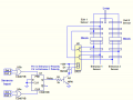
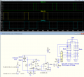
I know using a micro seems to be the preferred way to control the loop switchover here, but in case someone wants a simple logic design with no programming required, here's an alternate if IR sensors are used, which uses only one sensor at each entrance to the loop, and uses a delay to switch the polarities, as described by AH in Post #45:
It uses one CD4013 FF package, two transistors, two diodes, and 1 DPDT relay .

U1 is configured as a delay circuit to reverse the loop from the entrance polarity to the exit polarity after the delay.
The R3*C1 values shown give a delay of about 1 second, but the RC value can be varied to get a different delay, depending upon the layout characteristics, such as the distance from the entrance sensor to the entrance.

The sim shows the relay initially changing states to the entrance polarity and then, after the end of the train has passed the sensor and the delay, changing to the exit polarity, always maintaining the correct polarity for trains entering either entrance.

1714838241777.png
 
Last edited:

Thread Starter

AlbertHall

Joined Jun 4, 2014
12,660
U1 is configured as a delay circuit to reverse the loop from the entrance polarity to the exit polarity after the delay.
The R3*C1 values shown give a delay of about 1 second, but the RC value can be varied to get a different delay, depending upon the layout characteristics, such as the distance from the entrance sensor to the entrance.
I believe this would work except from my understanding of the poor translation of sensor operation I believe that the sensor output goes low on detection. This is why I like the uC method as this would be an easy change to the software, no soldering required.
 

JohnSan

Joined Sep 15, 2018
141
Ahaa..
Now I see.
So I have an idea- using an Arduino- which to my mind works.
I'll write it up Tuesday/ Wednesday as I'm away at the moment using a mobile phone.
Doesn't use extra 'sensors' and doesn't cause short circuits.
 

crutschow

Joined Mar 14, 2008
38,913
I believe that the sensor output goes low on detection.
Okay.
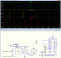
Here's the circuit for the IR sensor going low at detection:
Same number of parts, but used a 74HC74 flip-flop which has negative reset rather than positive.
This is why I like the uC method as this would be an easy change to the software, no soldering required.
Yes, the µC may be the preferred option if you know how to program, and I'm not arguing that.
My circuits are for those model train enthusiasts who don't, and don't want to learn (I expect there are a few), and find soldering a few terminals easier than programming.

1714881522879.png
 
Last edited:

JohnSan

Joined Sep 15, 2018
141
1714860403348.jpg
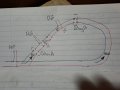
There are two sections of track, each slightly longer than max engine length. (Conducting wheels) . The voltage on each section is monitored. There are two relays. One feeding section A from lhs of the loop. One feeding section B from rhs of the loop.
Engine approaches CW.
Crosses onto section A.
FBA signal detected and relay A closes.
 
Top