Switch Mode Power supplies, My experience

Thread Starter

recklessrog

Joined May 23, 2013
985
There have been several members asking various questions regarding smp's, how to work on them safely, equipment required, (ring testers, esr meters, connecting oscilloscopes etc. With this in mind, and in no particular order are some of my experiences and recommendations based on over 50 years in electronics 22 of which where in servicing many different types of consumer electronics.
I am not saying that the advice I give is the only way, just that it worked well for my staff and myself and none of us died in the process of repairing thousands of devices.
Whether you want to repair a tv, computer power supply, use a wall wart to power your Arduino/Rasberry pi project or whatever I hope some of this will prove of use to you.
I will cover different aspects over a series of posts so that others can contribute, comment, and if need be, criticise.

So, first off I would like to show the usefulness of an inductor ring tester as this has cropped up lately on the forums.
When trying to diagnose a fault in a smp, the inductors are often overlooked as a possible cause. Maybe the resistance measurements look ok, maybe the inductance seems fine, but neither of these two tests are likely to show a shorted turn. Over 90% of the time, a ring test will.
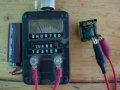
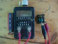
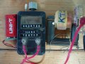
Here are pictures of my original home made ring tester (Dick Smith original circuit) testing a small inductor. The first shows a healthy "ring" the second is with a loosely coupled single turn of wire acting as a shorted turn. See the difference between the two by the number of Led's lit and the waveforms on the scope.P1010005.JPG P1010032.JPG P1010006.JPG P1010042.JPG
Notice that the second waveform is highly damped, the ring tester Led's still show the initial ring but the scope really shows the effect!
This test alone could save you money and time, because it is all to easy to find a shorted switching transistor, diode, high esr capacitor etc., replace them and still have a problem or even blow up the new parts.
Next time I get a moment, I will show how to test for other faulty parts with ring tester, and explain what "ringing" actually is and how the tester works. You can of course just google the subjects yourself, there is a wealth of info available.
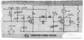
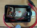
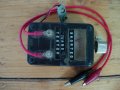
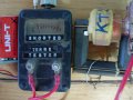
 

debe

Joined Sep 21, 2010
1,390
This is what I built & used for servicing TVs & SMPS about 40 yrs ago & has served me well over the years. It was an Electronics Australia circuit. Looks rough but it had to be compact to fit in the tool box.
 

Attachments

Thread Starter

recklessrog

Joined May 23, 2013
985
This is what I built & used for servicing TVs & SMPS about 40 yrs ago & has served me well over the years. It was an Electronics Australia circuit. Looks rough but it had to be compact to fit in the tool box.
I like it :).......Here is the original Dick Smith design that I built and am still using. (I have never changed the batteries and when I opened it earlier to take some pictures, the date end code for the Duracel's is, expires 2010 !!! well that is supposed to be when they have lost 20% of their charge in storage, and I think that they are supposed to have 10 year shelf life. If that is so, then they are 17 years old and still going strong!!!!! They may have been in stock for a while before I built the thing.
 

Attachments

debe

Joined Sep 21, 2010
1,390
Interesting fellow Bob Parker. He also designed a very usefull ESR meter. Ive built his MK1 & MK2 versions & found them invaluable over the years. & still use them.ESR METER.JPG
 

Thread Starter

recklessrog

Joined May 23, 2013
985
Continuing from my post with the ring tester, rather than getting bogged down with the theory of L/C resonance, I have uploaded a pdf of the original Dick Smith instructions which detail the operation and use of his design. (note... it is no longer available as a kit, but the blue ring tester is)
Doing this allows me to move on.
Another device that is in my view "essential" is an esr (equivalent series resistance) tester for electrolytic capacitors) Whilst many faulty capacitors are evident by bulging tops, gunge oozed out around the pins, and a a general appearance of of stress, I have replaced hundreds that look fine but have become high esr. As the esr rises and usually the capacitance drops, so the capacitor no longer does the job it's there for, causing faults that can be very confusing, from shut down, pulsing, wrong voltages, wavy patterns on displays due to excessive ripple on supply lines and a host of other strange effects.
This is where the esr tester comes into its own. In most cases, it enables you to test capacitors in circuit, but it is imperative to disconnect from the supply, and discharge them first. NOT with a screwdriver across the pins!! (more on how to do this properly later)
The one in the photo by debe in post #4 is the same one as I use and as you can see, it shows a comparative scale of samples taken from many examples of capacitors. This is a guide only! Some power supplies used in things like oscilloscopes and other test equipment, have capacitors specifically designated as "low esr".
I have a box full of such capacitors that I had to replace in a Phillips 'scope that was not behaving itself. Whilst many read within the limits shown on the tester, a good number showed significantly LOWER readings, this indicated to me that they had been selected for low esr. looking up the data sheet for them confirmed this. I replaced all the capacitors just to make sure that there was less chance of future failures. Doing this brought a 35 year old 'scope back to full health.
Anyone who repairs sky satellite receivers knows to not only change the capacitors, but to use uprated ones with low esr and a higher temperature rating. same goes for any power supply that gets very warm. 85 deg C capacitors have a hard time in power supplies, Use the 105 deg C or higher as replacements.
So, getting back to the tester, you've discharged them all havn't you? To do this safely and without risking blowing the end of your screwdriver off or the solder and pins off the capacitor, I use two old meter probes and a 2.5K wirewound 5 Watt resistor. (see the photo) P1010046.JPG Hold this across the capacitor terminals for 10 seconds and you should be ok to carry on testing. If you are at all unsure, check with a voltmeter first.
As with the ring tester and inductors, the esr tester can reveal faulty capacitors that otherwise would have thought to be ok....P1010026.JPG

Here are some pictures of other items I use.. P1010019.JPG..P1010001.JPG..P1010004.JPG..P1010016.JPG..P1010017.JPG..P1010020.JPG.. double click to see larger.

More to follow if anyone is interested :)
 

Attachments

Last edited:

Thread Starter

recklessrog

Joined May 23, 2013
985
Here are faulty capacitors and transformers that were quickly found with the aid of the esr and ring testers. I like to keep a few faulty parts for reference.

P1010050.JPG
 

Thread Starter

recklessrog

Joined May 23, 2013
985
This is what I'm up against sometimes, A friends son had "had a go" at fixing this smp, he found a short circuit diode and replaced it, promptly went bang when he turned it back on!
So, in went another diode but now it's dead so I get the thing sent to me with a note saying what he'd done and how he could not understand why it was not working considering he had "found the faulty part".
A quick visual showed that a capacitor had emptied itself into the ether with some force, this cap was connected to the diode he had replaced, except he put it in the wrong way round. It was meant to be a 12 -ve supply, (which he had assumed must be wrong, he even marked the pin on the connector with a red + sign over the silk screened - sign!!
So, having now spent an hour checking and replacing the diode and capacitor and testing it on load, it is all up and running ok. P1010021.JPG
 

Thread Starter

recklessrog

Joined May 23, 2013
985
After repairing any piece of equipment, it is always advisable to soak test it and stress test within it's specified parameters. This can save you additional time, cost and embarrassment when the owner returns within a short time ranting and raving!!
Here are a few pictures of the above smp being put through its paces......

P1010004.JPG P1010005.JPG P1010006.JPG P1010007a.JPG P1010010.JPG P1010008.JPG P1010014.JPG P1010002.JPG P1010003.JPG
Sorry for the slightly out of focus scope shots, but the camera has autofocus that cannot be turned off. In reality, the traces are pin sharp.
Here what I am testing is that the switching pulse changes correctly with varying input voltage and load applied. I built a current transformer into the Variac so that I can monitor the current drawn and see if it rises over time which could indicate that something is possibly underated/ unsuitable. This is an important check especially if you have used alternative semiconductors in the repair......Also checked is the undervolts protection if present is working, and does an overload condition shut it down properly. This is very important, as if it was able to supply current at an excessive level when there is a fault elsewhere in the equipment, a fire could result AND as the repairer you could be found responsible for the consequences.
Don't be tempted to make shortcuts in final testing, It's not only your reputation that can suffer if you neglect proper and reasonable testing.
 
Last edited:

Thread Starter

recklessrog

Joined May 23, 2013
985
Some members may know that I'm a "scopeaholic" I currently have about 8 or 9. ( you can never have too many lol) My favorites are the range of Phillips/Fluke, Fluke took over the oscilloscope branch of Phillips in the '90's and made an excellent series that ranged from 60MHz through to 200MHz, available as 2+2 channel, to true 4 channel and also combiscope digital storage versions.
I use the PM3394a digital storage one for most of my work as it is so versatile. ( I have two of these and the earlier PM3394, Two PM3092's and two PM3082's.
Recently, one of the pm3394a's was taking a long time to settle down, brightness was flickering, and a lot of noise on the trace even with the channel input set to ground. Bear in mind this was made in 1995 so is 22 years old and has been used for many thousands of hours with no other problems. The CRT's in these go on forever.
Knowing these 'scopes well, I decided to give it an overhaul. Common things to check would be electrolytic capacitors, and look for any dry joints cooked resistors, and any areas that show signs of heat stress. I removed the case and noticed that the X-Y main output amplifier board appeared a little cooked in the centre. (see picture) All the capacitors looked fine, no bulging, leaks, or shrunken plastic on the cases. None the less, I removed the board and unsoldered the capacitors. Measuring the 100volt 27mfd caps, showed two with an esr of 1.8, and two read over 3ohms. Not excessive, but it was the difference between them that made me suspicious. I did the same to the smp, and again most capacitors seemed fine but a couple where a bit on the high side but again not significantly so.
Not wishing to have to open the thing up again in the near future, I looked up all the capacitor values, and put in an order with a highly reputable major spares provider for a complete set of replacements. Cost inc. postage was less than £30.00. Two days later, they duly arrived.

As I have a copy of the service manual which has an overlay of component placement, I printed a copy and,....... take a note of this:- in the past with other equipment, I have discovered errors such as components placed the wrong way round etc. shown in the manuals. Always check with what you have in front of you!
If you are not experienced, or do not have an overlay, replace the parts "one at a time" it's all to easy to fit the wrong one if you've just stripped them all off the pcb.
So, with my overlay carefully checked, I marked the values of the capacitors on it and marked the polarity with red and black pens. Double checked again! Then, cup of coffee and out with my Denon SC-700Z desoldering tool, ( a must if you service for a living) and removed all the capacitors from both boards, (tinning the connections first helps the solder to be sucked cleanly away)
Using my overlay, I replaced the capacitors, soldering them with a medium point tip and high flux lead free solder.
When done, examine VERY carefully all the joints under a magnifying glass and good light, I use a fibre pen brush to clean each joint and make sure that there are no solder splashes, etc. Gave it a spray with pcb lacquer, and when dry fitted it all back together, connected up to the variac set at 120V and switched on!

BEAUTIFUL! quickly showed a noise free trace on the screen, and all is ok. I drilled a few holes in the case to let the heat out from the X-Y amplifier board and re-assembled everything and left it running for 8 hours then did a full re-calibration.
Working like a new one now :)
So here are a few pictures, the capacitors in the bag all measured fine, the suspect ones are next to it. At 22 years old, if some are failing, the others will follow soon and it simply is not worth penny pinching and only replacing a few.

P1010004.JPG P1010009.JPG P1010007.JPG P1010003.JPG Click on thumbnails for full image.
 
Last edited:

bwilliams60

Joined Nov 18, 2012
1,442
When scoping an SMPS, what specific points would you be looking at and what are you looking for? How many scope points would you say there are ina typical SMPS?
 

Thread Starter

recklessrog

Joined May 23, 2013
985
Hi, thank you for the interest :)
As a lot of inexperienced members may read this, I am writing a detailed post on "scoping switch mode power supplies" with an emphasis on how to do it safely and not blow up the scope, psu, or yourself. The terms "Earth" and Ground seem to be constantly misunderstood words, I prefer to define Zero reference point, and Earth as in the earth pin of the house supply separately.
So to answer your question, Mainly having determined there are no blown fuses, major shorts and no obvious burnt or blown components. I would want to see if there is drive to the main switching transformer, the terminal that goes to the semiconductor that connects to it which maybe an i.c, Mosfet, bipolar etc.Then in combination of voltage checks, I would check drive to the mosfet or whatever, check secondary supply etc.
In a short reply like this, I can't go into great detail, but will in a future post. The presence and detail of the waveforms, is the key. I.e if present, are they what i would expect or are they heavily damped, low, cycling etc This info tells me whether the fault is in the primary drive circuit, secondary output, shut down, feedback control etc.
It is difficult without showing real life examples of good/ bad scope traces to explain further, so watch this space.
 
Last edited:

Thread Starter

recklessrog

Joined May 23, 2013
985
I should have mentioned this earlier, three things that are invaluable in tracing problems that are intermittent, or "stops working after an hour mate" (in the words of a customer)
Thermal faults and some dry joints can be the devil to track down. Two of these piece's of "equipment" are cheap as chips but worth their weight in gold. I'm referring of course to freezer spray and a heat gun (or hair dryer)
By warming up the suspect area gently with the heat gun until the fault shows, judicious little blasts with the freezer can localise the fault area quickly.
My de-solderer also blows hot air so I can then focus the heat more precisely at individual components/joints.
This well known trick must have saved millions of wasted man hours in the service industry, and as time is money, that too.
A personal tip:-.... you can buy a small can of freezer spray from electronic component suppliers not very cheaply, OR as I do, go to a local plumbing supplier and buy pipe freezer in a big can cheaply. The can in the photo is two years old and still half full, and I use it a lot.


P1010001.JPG P1010003.JPG
 

Thread Starter

recklessrog

Joined May 23, 2013
985
Hopefully not too far off topic, but for anyone starting out, here is my personal experience learning about SMPS by debugging and fixing my old audio amplifier (with a ton of help from the crowd), which had a few parts bad in the SMPS section:


https://forum.allaboutcircuits.com/...phoenix-gold-ms250-1990-vintage.116368/page-4

Very Interesting, thanks, Nice to see that you didn't give up and the help you got from the other members :) Dogeydave knows his stuff !!
I think where a lot of people go wrong is that they don't understand the different sections of smps and how they interact with each other. Mind you, even when you do, without the correct sequence of testing and basic equipment required they can lead you on a merry old dance!!!

Even now, I look at the newer ones with components so small that I have to use a usb digital microscope to identify parts and say a silent prayer before I start!!!
 

Sensacell

Joined Jun 19, 2012
3,451
This is a very interesting thread!

What would be super amazing is to boil this down to a troubleshooting tree that guides one through the basics of repairing these beasts.
Since SMPS are a staple of every modern electronic product, there is a large demand for understandable repair information.

A real-world approach based on experience, incorporating the wisdom and tricks learned over years of doing it, my god! it could even be a book!
 

Thread Starter

recklessrog

Joined May 23, 2013
985
This is a very interesting thread!

What would be super amazing is to boil this down to a troubleshooting tree that guides one through the basics of repairing these beasts.
Since SMPS are a staple of every modern electronic product, there is a large demand for understandable repair information.

A real-world approach based on experience, incorporating the wisdom and tricks learned over years of doing it, my god! it could even be a book!
That is what I was hoping his thread would do, enable others to pop in their experiences and reference's where applicable. The problem with writing a book is similar to a musician writing a song, playing all the instruments etc himself. It becomes somewhat sterile and ends up like "this is the only way to do it" That is why I stated at the outset, these are my experiences (often learned the hard way) Others who read this may achive the same results but with a different method.
My PRIMARY aim is how to do it as safely as possible and point out potential hazards and pitfalls.
I was asked why I have a 15 Watt bulb with just an earth wire. Well it is exactly that, a mains plug with only a wire from the supply earth, through the bulb to a lead with a crocodile clip on the end. As there are"hot" and "cold" ground reference planes on smp's, I need to be VERY sure that even though I have a very good Galvanic isolation transformer, There is always a remote possibility that, A) I could accidentally plug the psu into a live non isolated socket, or, B) even more remotely but not impossible, the transformer could develop a short between the primary and secondary windings thereby putting me at risk of a lethal shock. By connecting the bulb to the "hot" side ground plane not only would give me instant warning by lighting up, and tripping the RCD protector. It also reassures that I can connect the ground of my scope or other test instrument without risk to that too. A seemingly minor thing to do, but complacency and shortcuts have a nasty habit of biting you when you least expect it.
I keep in mind that " ELECTRICITY," most times, you can't see it, hear it or smell it, but if you touch it, it can kill you!!..... I quite like living lol.
So if anyone has input to add to this thread, I will be very pleased to see your contributions because as Sensacell rightly says, smp's are now the staple of modern electronic power supplies.
Read every description you can find on how they work, manufacturers like ON semiconductors and others publish free downloadable tutorials and guides.
Get hold of a couple of old atx psu's and start identifying the different sections, look up the data on the I.C's and gain some experience with them. They may seem a black art, but in reality, once you know the working principles, they are just another piece of straightforward electronics that work on well founded basic techniques.
 
Last edited:

Thread Starter

recklessrog

Joined May 23, 2013
985
Top