Switch Component Recommendation

Thread Starter

ksandell

Joined Jan 23, 2020
9
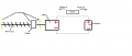
Hobbyist trying to design a device with as few mechanical parts as possible, i.e. no micro switches. In the attached drawing when the switch is moved to Position B the shuttle would move towards the motor and when the open contact circuit is completed, when the shuttle makes contact, the motor would stop. Moving the switch to Position A would result in the motor running with reverse polarity and carry the shuttle towards the other contacts, which would have the same effect upon contact. Obviously the drawing is very simple and I purposely left out wiring to keep it clean. I thought a Transistor of some sort would do it, but I'm not sure. And I may be completely overthinking this whole thing. What would be the best way to complete this circuit, or approach solving this? Thanks!
 

Attachments

ci139

Joined Jul 11, 2016
1,898
a conducting beam (rail) "under" the suttle that ends before the stop positions
however the rail should continue with a dielectric possibly ramping up at it's start - to ensure no contact
┮────┭ -- to avoid sparking you can use that contact to trigger ON/OFF transitor/Mosfet
to avoid using active components and/or sliding contacts - you can use an automotive relay contacts (requires a reliable mechanical control mechanism)
↑↑ the drawback of what is - you need a startup timer that powers the motor until the (shuttle moves to where the) rail starts conducting
or use doble rails , each of which only won't conduct at one end . . .
___________
Option B (your current setup) ::
  1. enable power , polarity to the circuit at switch swapp in between A,B
  2. disable power at contact at the ends of the worm gear
▲ this requires a (not so , but still more) complex circuitry (than just 1 transistor)
the design will be dependent on - of how fast you need to re-trigger the motor after it's stopped
..
the Falstad simulation . . . "a lot" of controls (i just tiled it up from the pricipial control blocks - it may be possible to optimize it - the component count . . . )
the explanation ::
• when the shuttle moves to an end the contact pulse triggers a 1 OFF pulse timer for reliable TURN OFF (the motor direction can be and swapped in here by OFF pulse if the start time/delay is critical)
• when switch position is changed -- that change is detected -- motor direction is adjusted --and-- power is enabled until it's TURNED OFF
▲ the Simulation lacks the 1 OFF pulse timer - that would take the LOW going pulse of the OC comparator as the Shuttle's endpoint contact . . . much the same as the upper rightmost 2x(2xNAND) (SR-trigger)-timer (basically it means the comparator and it's biasing network leaves off as it "emulates" the Shuttle's travel time)
▲ the Simulation is just a theoretical example that handles the problems involved (where some mosfet biasings are not very good) -- the actual practical design may differ from that a lot (by components used, etc. ...)
 
Last edited:

dendad

Joined Feb 20, 2016
4,474
Why no microswitches? That would be easier than making your own limit switches.
I think something like this...

MotorReverse.jpg

The diodes need to be rated higher that the stall current of the motor.
 

MaxHeadRoom

Joined Jul 18, 2013
28,682
You could also do it with a sensor on the motor shaft for e.g. and just count No. of revs each way.
If you don't want say proximity sensors out on the machine.
A few more details of the mechanics may help.
Max.
 

Thread Starter

ksandell

Joined Jan 23, 2020
9
You could also do it with a sensor on the motor shaft for e.g. and just count No. of revs each way.
If you don't want say proximity sensors out on the machine.
A few more details of the mechanics may help.
Max.
Thanks. I did consider a revolution sensor as you suggested, but I don't have much faith in them maintaining accurate end points. I have a gate opener on my property and I have to periodically reset it. Don't want to have to deal with that in this case since access will be an issue after I am done.
 

Thread Starter

ksandell

Joined Jan 23, 2020
9
a conducting beam (rail) "under" the suttle that ends before the stop positions
however the rail should continue with a dielectric possibly ramping up at it's start - to ensure no contact
┮────┭ -- to avoid sparking you can use that contact to trigger ON/OFF transitor/Mosfet
to avoid using active components and/or sliding contacts - you can use an automotive relay contacts (requires a reliable mechanical control mechanism)
↑↑ the drawback of what is - you need a startup timer that powers the motor until the (shuttle moves to where the) rail starts conducting
or use doble rails , each of which only won't conduct at one end . . .
___________
Option B (your current setup) ::
  1. enable power , polarity to the circuit at switch swapp in between A,B
  2. disable power at contact at the ends of the worm gear
▲ this requires a (not so , but still more) complex circuitry (than just 1 transistor)
the design will be dependent on - of how fast you need to re-trigger the motor after it's stopped
I'd be interested in learning more about Option B if you care to share. Thanks!
 

MaxHeadRoom

Joined Jul 18, 2013
28,682
I don't have much faith in them maintaining accurate end points. I have a gate opener on my property and I have to periodically reset it. Don't want to have to deal with that in this case since access will be an issue after I am done.
They can take all forms, depending on the design and if you can do a DIY version also.
You mention you want to design it, can you program a small PicMicro for example? Or build semi conductor circuits?
Max.
 

Reloadron

Joined Jan 15, 2015
7,515
Usually prox are solid state, open collector? ;)
Max.
Yes usually they are but I have seen some which offer a SPDT output. Pepperl & Fuch I think (operative word think) offer a few. The biggest problem with retiring is I forget all the manufacturer's names I once bought. OK, I found them, here is an example, they claim Relay Output rated 6 Amps AC or DC but they also call out a resistive load.

I guess one could also just use a SPDT reed switch but would need to hang a magnet on the trolley. I haven't seen any mention of motor current? While it would add to the parts count I guess any number of prox switches could be used NPN or PNP output open collector. Then too, as mentioned using a beam break is another option. I guess it depends on what the thread starter wants and the motor specifications.

Ron
 

Thread Starter

ksandell

Joined Jan 23, 2020
9
Yes usually they are but I have seen some which offer a SPDT output. Pepperl & Fuch I think (operative word think) offer a few. The biggest problem with retiring is I forget all the manufacturer's names I once bought. OK, I found them, here is an example, they claim Relay Output rated 6 Amps AC or DC but they also call out a resistive load.

I guess one could also just use a SPDT reed switch but would need to hang a magnet on the trolley. I haven't seen any mention of motor current? While it would add to the parts count I guess any number of prox switches could be used NPN or PNP output open collector. Then too, as mentioned using a beam break is another option. I guess it depends on what the thread starter wants and the motor specifications.

Ron
Sorry. I should have provided some context for the motor. Think miniature. Motor voltage will probably be somewhere in the 3v range with very small load.
 

Thread Starter

ksandell

Joined Jan 23, 2020
9
They can take all forms, depending on the design and if you can do a DIY version also.
You mention you want to design it, can you program a small PicMicro for example? Or build semi conductor circuits?
Max.
Thanks for the vote of confidence, but I'm not trying to be that ambitious. I'm just an old fool. :)
 

Reloadron

Joined Jan 15, 2015
7,515
Sorry. I should have provided some context for the motor. Think miniature. Motor voltage will probably be somewhere in the 3v range with very small load.
With that in mind you could likely just use a few simple proximity switches another possible would be placing a small magnet on the trolley and using a few SPDT (Single Pole Double Throw) reed switches. Another possibility is a photo sensor and beam. You can buy LASER diodes pretty cheap and the LASER sensors as well. The problem with most of these methods is the need for additional parts.

I haven't a clue why the opposition to a lever actuated mechanical micro-switch but all things considered it would be my first choice as to simple, efficient and they can last tens of thousands of cycles, even the cheap ones like I linked to. Based on your post you aren't really switching any current to speak of.

Ron
 

Thread Starter

ksandell

Joined Jan 23, 2020
9
With that in mind you could likely just use a few simple proximity switches another possible would be placing a small magnet on the trolley and using a few SPDT (Single Pole Double Throw) reed switches. Another possibility is a photo sensor and beam. You can buy LASER diodes pretty cheap and the LASER sensors as well. The problem with most of these methods is the need for additional parts.

I haven't a clue why the opposition to a lever actuated mechanical micro-switch but all things considered it would be my first choice as to simple, efficient and they can last tens of thousands of cycles, even the cheap ones like I linked to. Based on your post you aren't really switching any current to speak of.

Ron
Thanks for the info Ron. Maybe miniature was an overstatement. Think microscopic; or somewhere in between. The trolley will be attached to an enclosing tube with little clearance and only 1 end of the worm gear would really be in a place to use a micro switch.

I also thought about maybe some kind of over current cutoff when the trolley reaches the end of the travel and bottoms out, but I kinda felt like that may eat up battery power unnecessarily each time it goes through the cycle; and some over current electronic schematics I've looked at seemed pretty complicated. Trying to keep it simple, which may be a lofty goal, and also within very tight physical parameters.
 

Reloadron

Joined Jan 15, 2015
7,515
Thanks for the info Ron. Maybe miniature was an overstatement. Think microscopic; or somewhere in between. The trolley will be attached to an enclosing tube with little clearance and only 1 end of the worm gear would really be in a place to use a micro switch.

I also thought about maybe some kind of over current cutoff when the trolley reaches the end of the travel and bottoms out, but I kinda felt like that may eat up battery power unnecessarily each time it goes through the cycle; and some over current electronic schematics I've looked at seemed pretty complicated. Trying to keep it simple, which may be a lofty goal, and also within very tight physical parameters.
This will take some thought. :)

Ron
 

Thread Starter

ksandell

Joined Jan 23, 2020
9
I really think you need to supply some real specs and info. So far, your description is very vague. If you want help, please give us the courtesy of a full explanation.
You're absolutely correct that would make this much easier. However, I am just in the idea stage as it relates to the applicability of various components. Thinking through various options. I did note in the original post that micro switches would not work and that I was interested in some type of small solid state electronic component that could act as a switch with further clarification that it was low voltage and low amperage. So if you have some ideas I am open to hearing them. Sorry, I just don't know much about electronics. Thanks for your understanding.
 

Thread Starter

ksandell

Joined Jan 23, 2020
9
This will take some thought. :)

Ron
Thanks I can figure out the organization of electronic components and paths of current, just need to figure out what small, solid state electronic device that can act as a switch without drawing power (or nominal power) when engaged, or rather creates an open circuit. Thanks!
 

dendad

Joined Feb 20, 2016
4,474
This sounds like a good intro project for an Arduino and a motor drive H bridge.
This way, it will be easy to also control the speed. And if you add a pot somehow, the position.
The end points could be sensed with a couple of Hall switches and magnets.
 
Top