Switch Between two cmos bridges-rectifier

Thread Starter

Giannis Bougas

Joined Jun 11, 2018
12
Hi everyone, I write a new post because I didn't find something like this. Sorry if there is.

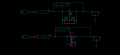
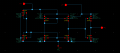
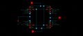
I want your ideas, in my thesis I created two full bridges rectifier, one in DTMOS and the other in BTMOS. In DTMOS the bridge works in range of 0,10V to 0,73V. In BTMOS works in 0,73 to 3,5V. Now I have to create a complete system with these two bridges and I need a "circuit" for switching between the bridges. Do you have any ideas?
The all system is created in cmos AMS 0.35.
Sorry for my english!
Thank you !
 

Thread Starter

Giannis Bougas

Joined Jun 11, 2018
12
I want a circuit which chooses the dtmos bridge for voltages from 0.1 to 0.73 and chooses the btmos bridge for voltages from 0.73 to 3.5
 

Thread Starter

Giannis Bougas

Joined Jun 11, 2018
12
I already deleted two of them, if you using computer to uploaded them then you should check the mouse key maybe had bounce.

And the words were not clear enough.
The words on the picture? The picture has the two bridges with bulk regulation, now I have to put one ac source and switch between them.
 

Thread Starter

Giannis Bougas

Joined Jun 11, 2018
12
I can't identify the channels of MOSFET that which one is N or P channel? (the symbols do not clear, like DTMOS)
And what is the fbr, is that the Full Bridge Rectifier?
Yes, fbr=full bridge rectifier, DTMOS is a bridge but the blcs of pmos are conected on their gate. Βut this is not important. I have two bridges and I want, with some way to switch between them. For example a peak detector is good for this work?
 

ScottWang

Joined Aug 23, 2012
7,397
Yes, fbr=full bridge rectifier, DTMOS is a bridge but the blcs of pmos are conected on their gate. Βut this is not important. I have two bridges and I want, with some way to switch between them. For example a peak detector is good for this work?
Could you rewrite the text of label for the MOSFET, which one is Nmos and which one is Pmos, an unclear picture or circuit may causes the members won't help you, they might ignore the thread, and you will loss a good chance to have some good members which have the good skills to help you.
 

Thread Starter

Giannis Bougas

Joined Jun 11, 2018
12
Could you rewrite the text of label for the MOSFET, which one is Nmos and which one is Pmos, an unclear picture or circuit may causes the members won't help you, they might ignore the thread, and you will loss a good chance to have some good members which have the good skills to help you.
 

Attachments

ScottWang

Joined Aug 23, 2012
7,397
About the circuit of fbr and DTMOS, I'm not sure is that the label was wrong or the symbol was wrong, you labeled the N-ch as P-ch, and labeled the P-ch as N-ch?

About the circuit of comparator, the symbols were not clear that which pin is D or S?
The symbols on the circuit of fbr and DTMOS are very clear for the pins.
 

Thread Starter

Giannis Bougas

Joined Jun 11, 2018
12
About the circuit of fbr and DTMOS, I'm not sure is that the label was wrong or the symbol was wrong, you labeled the N-ch as P-ch, and labeled the P-ch as N-ch?

About the circuit of comparator, the symbols were not clear that which pin is D or S?
The symbols on the circuit of fbr and DTMOS are very clear for the pins.
I check all these DTMOS, FBR and COMPARATOR and work well. The question is how I can to switch between two bridges because I want to use for low voltages the DTMOS and for high voltages the FBR.
 

ScottWang

Joined Aug 23, 2012
7,397
I created two full bridges rectifier, one in DTMOS and the other in BTMOS. In DTMOS the bridge works in range of 0,10V to 0,73V. In BTMOS works in 0,73 to 3,5V. Now I have to create a complete system with these two bridges and I need a "circuit" for switching between the bridges.
So the FBR was made by BTMOS and it works from 0,73 to 3,5V?

The question is how I can to switch between two bridges because I want to use for low voltages the DTMOS and for high voltages the FBR.
Since their Input/Output voltage are different, why you want to switch them and where do you want to switch, Input or Output side?

And are they never working in the same time?

How much current of both voltages?
 

Thread Starter

Giannis Bougas

Joined Jun 11, 2018
12
So the FBR was made by BTMOS and it works from 0,73 to 3,5V?


Since their Input/Output voltage are different, why you want to switch them and where do you want to switch, Input or Output side?

And are they never working in the same time?

How much current of both voltages?
Firstly I wanted to switch them to the input. Now I think if I can to switch them in the output viz I think if there is a way to connect the capacitors in the output and after this is driven to the same load.
 

Attachments

ScottWang

Joined Aug 23, 2012
7,397
DPDT in a chip? How? In the input,viz after ac source?
What I thought was used the switch to switching the FBR and DTMOS FBR from input side and it is an external component.

I have had asked the questions in #14, but you didn't give me the answer, during that time that I even thought about maybe can be control from the inside of FBR and DTMOS FBR to choose which one is Enable and which one is disable (just a thought), and I also asked about the current the end of the #16, you just said that the circuit was working fine, maybe you already limited the number of pinout only 4 pins for the FBR and DTMOS FBR, and controlling from the side might add some more components.
 
Top