Switch between 5V power supply and 6.6 battery

sghioto

Joined Dec 31, 2017
8,664
I agree with you that 5 mA is not a lot but my device should work with battery for at least 2 years.
You said in post #3 that the load current is 400 to 500 ma so what's another 5 ma when on battery power, that's only an extra 1% at most. Is the device not always on?
SG
 

Thread Starter

hesan621

Joined Apr 23, 2011
13
You said in post #3 that the load current is 400 to 500 ma so what's another 5 ma when on battery power, that's only an extra 1% at most. Is the device not always on?
SG
The device includes a sensor and an actuator.
As long as the sensor is not Stimulated, the current consumption is about 20 mA. When the sensor is Stimulated, the actuator is activated for a few seconds and consumes a current of about 400 mA.So I think the 5 ma is important.
 

ScottWang

Joined Aug 23, 2012
7,503
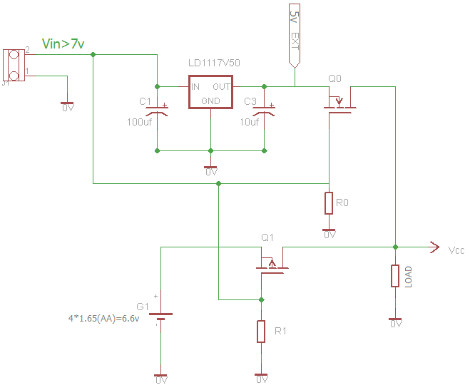
I improved the circuit.

I think with this improvement, the minimum Vgs is 0.4v and we can be sure that Q1 is off.(Is it true?)
Also, I replaced the schottky diode (D1) with the NMOS (Q0) , which has a negligible drop in 5v.(Is it true?)
If you want then you can in series with two 1N4001~4007 between Q1 and the output that it will close to 5V, if you want it's voltage close to D1 then you can in series with 3 1N4001~4007.
 

crutschow

Joined Mar 14, 2008
38,573
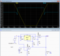
Below is the LTspice simulation of your circuit in post #16.
I didn't have a model for the LD1117 regulator, so I used the common LM317.
M1 must be a logic-level type N-MOSFET with a Vgs max threshold of <2V.

upload_2018-11-3_11-37-5.png
 

Thread Starter

hesan621

Joined Apr 23, 2011
13
If you want then you can in series with two 1N4001~4007 between Q1 and the output that it will close to 5V, if you want it's voltage close to D1 then you can in series with 3 1N4001~4007.
Thanks ScottWang.
I don't want to bring the Q1 output to nearly 5V, because the Maximum output voltage acceptable for next stage circuit is 6.6 v.I couldn't find a 6v LDO, so I used a 5v LDO.
 

ScottWang

Joined Aug 23, 2012
7,503
Thanks ScottWang.
I don't want to bring the Q1 output to nearly 5V, because the Maximum output voltage acceptable for next stage circuit is 6.6 v.I couldn't find a 6v LDO, so I used a 5v LDO.
You can choose LM317 and setup to 6V output, and it needs 9V input, the 78M06 is 6V output for 9V input, but it only can provides 500mA output current, so it can't afford the load needed.
 
Top