You need a way to turn it on. A lack of a positive voltage on the USB is not the same as pulling the gate low.
To specify a MOSFET, you need to specify the current rating. Any particulars that might matter need to be mentioned as well, such as package size, surface mount or not, and so on.
You need a way to turn it on. A lack of a positive voltage on the USB is not the same as pulling the gate low.
To specify a MOSFET, you need to specify the current rating. Any particulars that might matter need to be mentioned as well, such as package size, surface mount or not, and so on.
Problem previous circuit:
Since battery voltage is greater than the 5V supply, the MOSFET body diode will always conduct, so I've always be draining the battery.
I reversed source and drain to solve that.
That seems reasonable at first glance. I didn't really study the details but the current rating and basic type seem good.
One problem with your circuit is the power lost across that diode when powering the load off the 5V source, and the voltage reduction there. If neither of those are a concern, it's fine.
A possible problem with the circuit in post #8 is the the Vgs of Q1 is -1.6V when the 5V is available, and that may be enough to partially turn on a logic-level MOSFET.
The circuit below (although more complicated) is better for that purpose:
Q2 could be a P-MOSFET if you prefer.
A possible problem with the circuit in post #8 is the the Vgs of Q1 is -1.6V when the 5V is available, and that may be enough to partially turn on a logic-level MOSFET.
The circuit below (although more complicated) is better for that purpose:
Q2 could be a P-MOSFET if you prefer.
Let's consider different situations.
For the circuit below, I considered four different situations.
1)External 5v is connected and battery is at the maximum voltage(6.6v)
Vgs=-1.6v : In this situation, for proper circuit operation, Q1 must be off.
2)External 5v is connected and battery is at the minimum voltage(4v)
Vgs=1 : In this situation, for proper circuit operation, Q1 must be off.
3)Eternal 5v is disconnected and battery is at the maximum voltage(6.6v)
Vgs=-6.6v : In this situation, for proper circuit operation, Q1 must be on.
4)Eternal 5v is disconnected and battery is at the minimum voltage(4v)
Vgs=-4v : In this situation, for proper circuit operation, Q1 must be on.
-----------------------------------------------------------------------------------------------------
Now let's look at the datasheet of two MOSFETS. FDN340P(or FDN304P) & FDN360P
According to datasheets,when Vgs=1v (situation 2) : Mosfet is Off ,which is good for us.
When Vgs= -6.6v(situation 3) : Q1 is On,Which is convenient for us.
When Vgs=-4v (situation 4) : Q1 is On,that is a good news.
When Vgs=-1.6v (situation1) : Q1 does not seem to be completely off.
--------------------------------------------------------------------------------------------------------
Are my conclusions from the datasheets correct?
This is what I suggest:
1. You need a transistor without an internal diode so you switch the source and drain.
2. You need a transistor with Vgs threshold "-2" to "-4VDC".
3. You need a zener diode near the source to limit the battery voltage to "5VDC".
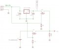
I improved the circuit.
I think with this improvement, the minimum Vgs is 0.4v and we can be sure that Q1 is off.(Is it true?)
Also, I replaced the schottky diode (D1) with the NMOS (Q0) , which has a negligible drop in 5v.(Is it true?)
I think its possible to fix that with a logical element on the gate?
This is what I suggest:
1. You need a transistor without an internal diode so you switch the source and drain.
2. You need a transistor with Vgs threshold "-2" to "-4VDC".
3. You need a zener diode near the source to limit the battery voltage to "5VDC".
about suggestion first and second, do you know part number of mosfet?
About your first and second suggestions, can you say a part number of mosfet?
But about third suggestion,I don't like adding a zener diode.Because I don't want an extra current (zener current) to be pulled from batteries.
about suggestion first and second, do you know part number of mosfet?
َAbout your first and second suggestions, can you say part number mosfet?
But about third suggestion,I don't like adding a zener diode.Because I don't want an extra current (zener current) to be pulled from batteries.
I agree with you that 5 mA is not a lot but my device should work with battery for at least 2 years.
Typical quiescent current of AMS1117 is about 5 mA.
Instead of using a zener on the battery output, I can transfer the regulator to the end of the circuit.
In this case, if Q1 switches the battery voltage, the battery output will be connected to the input of the regulator and the output voltage of the circuit will be 5 volts. But , the quiescent current of the regulator will also be pulled from batteries which is not suitable for a low power circuit.
 Facebook
 Google
 GitHub
 Linkedin