Facebook
 Google
 GitHub
 Linkedin
Hi, I have a linear actuator which I purchased to open my gate remotely. This has automatic stops at the extended and retracted position. The current to the 12v motor is reversed to change from opening to closing.
I have found it impossible to match the stops at the fully opened and fully closed position.
I have decided on an excellent way to stop power to the actuator when the gate is closed or opened. But it needs a smart circuit design which is beyond me. I have tried flip flops, latching ics etc not physically but at a design stage and have got hopelessly confused.
The first obstruction to the gate movement is at the gate closed position where it cannot move any further. I can make an obstruction at the gate open position. I have used a 1 amp fuse in the circuit which blows when the gate meets an obstruction protecting the motor. When a dc motor is overloaded it draws more current.
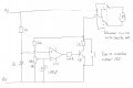
I want this smart circuit to stop power to the actuator when the current to the motor exceeds 1 amp. When the current to the motor is reversed I want power to the actuator to be restored thereby moving the gate in the other direction.
Such a circuit may already be available or if not can any of you smart guys on the forum design such a circuit for me? Thanks in advance.
I have found it impossible to match the stops at the fully opened and fully closed position.
I have decided on an excellent way to stop power to the actuator when the gate is closed or opened. But it needs a smart circuit design which is beyond me. I have tried flip flops, latching ics etc not physically but at a design stage and have got hopelessly confused.
The first obstruction to the gate movement is at the gate closed position where it cannot move any further. I can make an obstruction at the gate open position. I have used a 1 amp fuse in the circuit which blows when the gate meets an obstruction protecting the motor. When a dc motor is overloaded it draws more current.
I want this smart circuit to stop power to the actuator when the current to the motor exceeds 1 amp. When the current to the motor is reversed I want power to the actuator to be restored thereby moving the gate in the other direction.
Such a circuit may already be available or if not can any of you smart guys on the forum design such a circuit for me? Thanks in advance.