super cap instant charge station

Thread Starter

Capernicus

Joined Jun 24, 2022
87
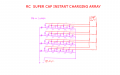
If you make this array large enough (without enough parallel lines) the global resistance will drop enough for it to charge a super capacitor in less than 10 seconds maybe.

And no step down transformer required. It may be a large array, but I think 1/4 watt components is all you need because the power is nicely spread out throughout it, so its very cheap! or it can also work nicely with nyckel chrome wire!

So next time I go to the electronics shop, I'm going to see if I can charge my 3000 farad super cap in less than 10 seconds just off a 30v 3a power supply, that would be cool if it works.

The only problem is if the powersupply comes off the series charging lines down the parallel lines. (thats what the resistors are there for) then that will stuff it, but its wired so that doesnt happen hopefully.

so its either winding a transformer, or building this rc array, they both probably take some time, but either way its fairly cheap. But since I'm into capacitors ill give this one a whirl and see if it works.
 

Attachments

Ya’akov

Joined Jan 27, 2019
9,069
It would be simpler to use take a larger supercap and charge it slowly and then use that cap to charge a smaller one more quickly.

In any case TANSTAAFL, the power is either going to come from the PS or you will be spending time collecting it beforehand so the utility is limited to such cases where the device using the supercap to be charged doesn’t discharge it faster than you can charge a different capacitor (or bank).

But even if your arrangement “works” it’s overly complex given that much smaller and available arrays of supercaps are readily available.
 

Thread Starter

Capernicus

Joined Jun 24, 2022
87
Oh, and you can calculate the fastest theorectial charge with 3A if you know the ESR of the capacitor.
you want low esr for the little charging capacitors in the array, i think 1pf caps have low esr so you should be right, but the charging is actually timed with resistors in this, if it ends up too much ohms then you just have to build more lines till you get to the time budget you want. (10 seconds? :))

Theres going to be voltage loss, so dont just plug it straight into the capacitor, do it with a test cap first to see if the voltage is right given so much power supply voltage, because theres going to be some unknown loss there that u might want to just bodge the power supply to, to get to the 2.7 or so you need for the super cap.

Then the horrible situation of over volting sensitive super caps is always there, they are probably very easy to destroy/over volt, so dont leave it plugged into the VPS, or just accidentally nudge the nob a bit, and your cap is insta destroyed.
 

Ya’akov

Joined Jan 27, 2019
9,069
you want low esr for the little charging capacitors in the array, i think 1pf caps have low esr so you should be right, but the charging is actually timed with resistors in this, if it ends up too much ohms then you just have to build more lines till you get to the time budget you want. (10 seconds? :))

Theres going to be voltage loss, so dont just plug it straight into the capacitor, do it with a test cap first to see if the voltage is right given so much power supply voltage, because theres going to be some unknown loss there that u might want to just bodge the power supply to, to get to the 2.7 or so you need for the super cap.
Are you expecting your array to somehow decrease the charge time compared to the PS connected directly to the cap to be charged?
 

Thread Starter

Capernicus

Joined Jun 24, 2022
87
Are you expecting your array to somehow decrease the charge time compared to the PS connected directly to the cap to be charged?
yes. it lets you charge the cap at 5x the voltage, with 5 caps in series, so it gets 5x the speed boost.

If you have 100 caps in series, its 100x faster. (if u were doing it out of the wall socket, with 240volt.)

The increase you get is what you step down, (so u have to run it higher volts to get anything out of it. it just lets you charge at a higher volt than just the 2.7 volts.)
 

Ya’akov

Joined Jan 27, 2019
9,069
Capacitors store charge. The power supply is current limited. Any way you work it there is no more power than the supply produces. W=VA, so you can trade (always with a loss) between V and A but W is constant.

Where is the extra charge coming from?
 

Thread Starter

Capernicus

Joined Jun 24, 2022
87
Where is the extra charge coming from?
the extra charge is coming from running it at a higher volts than the voltage rating on the super cap.

Oh, wait. You are trying to make a capacitive dropper. You intend to power this with mains?
I dont know what a capacitive dropper is, but if you have 3 caps in series, its /3 volts on them each, as long as it charges evenly.
Im just going to run it at 30volts at first, I dont know how fast itll work, but itll be about 10x faster, than normal (which im not sure how much time that is.) with 30volt power supply.
 

AlbertHall

Joined Jun 4, 2014
12,343
as long as it charges evenly.
Aye, and there's the rub. Unless the capacitors have the same capacitance, which they won't, the voltages will not be equal. The lowest value capacitor will reach its maximum rated voltage before the others and continued charging of the array will likely destroy that capacitor.
 

Ya’akov

Joined Jan 27, 2019
9,069
I was referring to charge the noun, not the verb.

As I said, total power from a power supply cannot be increased by connecting something to its output (that isn’t a source of power itself). Current is the limiting factor in how quickly you can move charge around. Current is dependent on voltage, to be sure, but also on the resistance of the circuit.

So, assuming you were going to use a supply like the mains where the power (in the US) is around 1800W. That‘s all you have to work with. Anything you put after it will only reduce this. Obviously if you charging cap you are going to need DC, not AC so you have to rectify it. You also have to somehow limit the 170V or so that will be coming from the rectifier.

You can charge a supercap with higher voltage but you can never allow the capacitor to exceed its rated voltage. This is a delicate thing and you would have to provide some mechanism to prevent overcharge. No matter what the ESR of the capacitor will limit current.

The capacitor will also heat up. It is possible that it will heat up enough to degrade it over time. This is, of course, if it doesn’t blow up or arc through it’s internals.
 

Thread Starter

Capernicus

Joined Jun 24, 2022
87
Aye, and there's the rub. Unless the capacitors have the same capacitance, which they won't, the voltages will not be equal. The lowest value capacitor will reach its maximum rated voltage before the others and continued charging of the array will likely destroy that capacitor.
I think most people probably would just use a step down transformer and diode bridge and dont worry about all this RC madness, Its just something I got myself into trying to be some kind of pointless rebel.
 

BobTPH

Joined Jun 5, 2013
8,804
dV/dt = I / C

With I at 3A it can raise the voltage of the capacitor by 3 / 3000V or 1 mV per second.

To charge to 30V will take 30,000 seconds.

Now, you can do better than that, because the voltage is only 30V at the end of the charge cycle. A DC to DC converter can increase the current at lower voltage, so it will charge faster.

But the easy way to determine the theoretical fastest charging time is via an energy calculation.

The 30V 3A power supply can put out 90W, or 90 joules per second.

The energy in a capacitor is

E = 1/2 CV^2

So you need 1/2 x 30 x 30 x 3000 joules.

That is 1.35 MJ. At 90J per second, that is 15000 seconds.

So, good luck with your project!
 

Thread Starter

Capernicus

Joined Jun 24, 2022
87
Now, you can do better than that, because the voltage is only 30V at the end of the charge cycle. A DC to DC converter can increase the current at lower voltage, so it will charge faster.
Thats the idea, off I go to the shop and lets see if this cap can charge faster! shouldnt cost me too much, or I wind a transformer, but I'm sorta hooked on caps at the moment, so I Just need $10 worth of 1 puff caps and some nichrome, off I go.

Or in Disney speak: "Have a magical day"
I like the picture of the two men will the cool sausage hats!!
 

Ian0

Joined Aug 7, 2020
9,667
The faster you charge it the higher the losses will be.
Current x time = capacity
but loss is proportional to current^2
Charging at twice the current will take half the time, but will lose twice as much energy (FOUR times the power for half as long)
 

Ian0

Joined Aug 7, 2020
9,667
Have you not spotted the obvious flaw in your design?
From each point on your diagram where two capacitors connect you have one resistor to the positive terminal of your supercapacitor and one resistor the the negative terminal. That puts a 2Ω load on the supercapacitor for every node and you have 12 such nodes, so a load on the supercapacitor of 0.166Ω; so what it will do is discharge the supercapacitor at 16 Amps.
 

crutschow

Joined Mar 14, 2008
34,280
The faster you charge it the higher the losses will be.
The loss to resistively charge a capacitor is independent of the time to do the charge, or the value of resistance in series with the capacitor.
The loss is always equal to the energy stored on the capacitor (1/2 CV²).

The only way to reduce that loss is to resonantly charge the capacitor through an inductor (for a perfect inductor, there would be no loss).
 

Thread Starter

Capernicus

Joined Jun 24, 2022
87
Have you not spotted the obvious flaw in your design?
From each point on your diagram where two capacitors connect you have one resistor to the positive terminal of your supercapacitor and one resistor the the negative terminal. That puts a 2Ω load on the supercapacitor for every node and you have 12 such nodes, so a load on the supercapacitor of 0.166Ω; so what it will do is discharge the supercapacitor at 16 Amps.
All the parallel lines all have more voltage than the super cap so theres no reverse flow.


Note, there is voltage loss in the circuit, but I dont know exactly how much its going to be, I'm going to put a test cap in and check the volts on the charging side after I've built it.
 
Top