Stepper or DC? - moving battery operated motor back and forth

Thread Starter

riddhi.s

Joined Apr 13, 2023
24
rack & pinion, there are relatively cheap but apparently well made versions out there.
I looked into it and because it is going to probably add significantly to the cost and weight of the installation, we have kept it as a secondary option. We are surely going to try it if the installation proves to be inefficient. Plus, the hanging installation and wheels allow a slight error of margin in case of 2 rails being slightly uneven. We will have an issue with that if the rack and pinion are used.
 

Thread Starter

riddhi.s

Joined Apr 13, 2023
24
And what does that have to do with supporting even that rail over 100 meters? In the green house shown it would be simple, but this sound like it's outside, since the solar cell battery recharge was mentioned.
Again my apologies to everyone for not being at liberty to discuss more details and leaving a lot for guessing. In one installation type it will be in a slightly windy situation but in another it will be inside installation.
 

MaxHeadRoom

Joined Jul 18, 2013
30,708
I think that idea is intended to have a L.S. or Proximity SW, carried with the motor which would be triggered at each stop point by a suitable actuators positioned along the slide.
There may have to be logic to allow the camera carriage to move off the L.S. before triggering the next position.
 

Sensacell

Joined Jun 19, 2012
3,786
Based on the very long track concept, and the need to stop at a number of positions along the way, it seems like you need a really coarse form of absolute position feedback.
Then you can use a really simple friction drive, slight slippage would have no effect on the positioning accuracy.

I would use a cheap laser barcode scanner that would read printed stickers that you stick on the rails every few centimeters.
Put the stickers inside an upside-down "C" channel rail, so they don't get dirty too easily.

https://www.waveshare.com/barcode-scanner-module.htm
About $40 bucks.

Each sticker would be sequentially numbered to tell you where you are along the track.
No need to worry about loosing position, on cold start, you just drive until you find a sticker, then you are good to begin a scan knowing exactly where you are.

You can also program in deceleration zones, slew at full speed until you reach a given sticker, reduce speed, hunt for the stop sticker, stop. etc.
 

MisterBill2

Joined Jan 23, 2018
27,731
Several days ago I suggested counting wheel revolutions, given that slippage was not an issue. And I suggested a magnet and reed switch for minimum power consumption. A laser barcode scanner and the software it must have running will consume a fair amount of power.
And now I am reminding folks that it is entirely possible that the whole track installation as been built a while back,and so that cost may not be part of the discussion. And it is not clear that the whole "rail" assembly is not a monorail sort of setup.
 

Thread Starter

riddhi.s

Joined Apr 13, 2023
24
I would use a cheap laser barcode scanner that would read printed stickers that you stick on the rails every few centimeters.
Put the stickers inside an upside-down "C" channel rail, so they don't get dirty too easily.
https://www.waveshare.com/barcode-scanner-module.htm
About $40 bucks.
Compared to RFID, the stickers are cheaper. However, in terms of the power consumption it looks like the RFID scanners consume around 10mA while the barcode scanner takes 100mA+. Though I will surely do a bit more digging into this. Thanks for the advise.
 

Thread Starter

riddhi.s

Joined Apr 13, 2023
24
I think that idea is intended to have a L.S. or Proximity SW, carried with the motor which would be triggered at each stop point by a suitable actuators positioned along the slide.
There may have to be logic to allow the camera carriage to move off the L.S. before triggering the next position.
Could you please give me a couple of examples. I like the sound of it but my experience and/r knowledge seem to fall short.
 

Thread Starter

riddhi.s

Joined Apr 13, 2023
24
Several days ago I suggested counting wheel revolutions, given that slippage was not an issue. And I suggested a magnet and reed switch for minimum power consumption. A laser barcode scanner and the software it must have running will consume a fair amount of power.
And now I am reminding folks that it is entirely possible that the whole track installation as been built a while back,and so that cost may not be part of the discussion. And it is not clear that the whole "rail" assembly is not a monorail sort of setup.
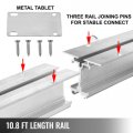
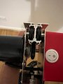
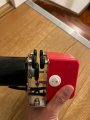
Thanks. The rail looks like the following and it is sort of upside down monorail, a simplified one though.

My carriage does not look exactly as the attached. however, i plan to use the same track, 4x carriage wheels and the driving wheel underneath with motor attached to it. my carriage will be slightly wider.

I'm just wondering.....would it be better to convert one of the 4 trolley wheels as a driving wheel and completely eliminate the current driving wheel that's underneath?
 

Attachments

LesJones

Joined Jan 8, 2017
4,509
Hi Max, Re your post #35 No I don't prefer a stepper. In simple terms if a normal DC motor was used with amicro switch sensor the contacts would just be in series with the motor and a short pulse shorting the micro switch would start it moving to the next stopping position. If the motor and power source were on the carriage a single micro switch would be used. I the motor and power source were fixed there would be a micro switch at each stopping point and the NC contacts on the micro switches wired in series. If the speed of movement was fast more sensors would be required to initiate a ramp down of the speed before the actual stopping position.

Les.
 

Sensacell

Joined Jun 19, 2012
3,786
Compared to RFID, the stickers are cheaper. However, in terms of the power consumption it looks like the RFID scanners consume around 10mA while the barcode scanner takes 100mA+. Though I will surely do a bit more digging into this. Thanks for the advise.
You would not need to look for the stickers very often, so the power could be rather low.
I wonder if you can stick RFID stickers on a conductive metallic surface and still read? Else you might need to mount them another way, which costs money too?
 

Sensacell

Joined Jun 19, 2012
3,786
Thanks. The rail looks like the following and it is sort of upside down monorail, a simplified one though.

My carriage does not look exactly as the attached. however, i plan to use the same track, 4x carriage wheels and the driving wheel underneath with motor attached to it. my carriage will be slightly wider.

I'm just wondering.....would it be better to convert one of the 4 trolley wheels as a driving wheel and completely eliminate the current driving wheel that's underneath?
Nope- this configuration allows the drive wheel to be preloaded into the rail to create the necessary friction.
 

LesJones

Joined Jan 8, 2017
4,509
Reading the thread again it looks like the motor and power source are on the carriage and that the stopping position location needs to be known. I think the stop number could just be a stop counter. It could be re initialised at each end of the track. At one end it would be set back to zero at the other end it could be set to the total number of stops plus 1. There would be a microswitch on each end of the carrage that would change the direction of travel, re initialize the stop counter and change between incrementing or decrementing the stop counter. I would suggest using just a microcontroller (PIC or Atmel) rather than an Arduino to reduce power consumption. Is the move from one stopping postition to the next just initiated on a time basis or is it controlled externaly ?
If it was external control then the HC12 modules could be used for the commubication
I thin some form of magnetic sensing (Reed switch or Hall sensor.) would be more relaiable than micro swtches (Humidity causing contact problems.) or optical sensors (Problems with insects in the light path.)

Les.
 
Last edited:

MisterBill2

Joined Jan 23, 2018
27,731
After viewing the pictures, it seems that a simple, easy, and cheap scheme for marking the stop locations will be a reed switch on a plastic bracket on top of the red portion of the trolley, and a magnet stuck to the upper surface of the rail so that it would close the reed switch for perhaps an inch of travel. The other benefit is that it will consume zero power while not active, and very little power when active. With a fairly strong magnet the positioning will not need to be extremely close.
This concept will be better than counting wheel revolutions.
At the track end a mechanical stop can operate a microswitch, or a magnet on the stop can activate a reed switch bracketed to the side of the red module. The benefit being the lack of power consumption.
An alternative approach will be three reed switches arranged to provide from the firs switch that the target position is being approached, with the middle reed switch indicating at the target location, and the last reed switch serving for the opposite direction.
With such a scheme it is likely that all of the control logic could be accomplished with "4000 series" CMOS devices, except for the actual motor driving commutation. That wold reduce the logic power consumption to the micro-amps level.
 
Last edited:

MrChips

Joined Oct 2, 2009
34,948
Instead of the drive on the carriage, how about a very long rope wrapped around two pulleys at the ends of the rail?

One pulley is driven by a motor with an optical encoder or simply use a stepper motor.
 

MaxHeadRoom

Joined Jul 18, 2013
30,708
Could you please give me a couple of examples. I like the sound of it but my experience and/r knowledge seem to fall short.
What I intended was instead of having a stop sensor at each location, was to have one sensor mounted on the carriage where a actuator would trip or operate the same sensor at each location, steps would be needed when a move was commanded in order to ignore the limit momentarily until the carriage cleared it.
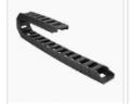
Another issue arises, what form of cabling support is intended?
The three common ones are Cable Chain, Festoon & recoil drum, with the first being the most practical IMO.

Igus Cable Chain

1681565447985.png
 

MisterBill2

Joined Jan 23, 2018
27,731
Instead of the drive on the carriage, how about a very long rope wrapped around two pulleys at the ends of the rail?

One pulley is driven by a motor with an optical encoder or simply use a stepper motor.
Keep in mind that friction is the enemy of battery power.
The "long rope" would be a problem if there are curves in the track. At 100Meters, it would also wind a whole lot onto the reels at the ends. And it would consume more power. Besides that there would need to be communications with both motors. And untangling even one mishap would be a serious challenge.
The IGUS CHAIN is expensive.
Since the carriage already carries the battery pack, why add external power consumption? The one option that could reduce drag would be roller chain with a drive sprocket on the motor. But if the track curves that would require a lot of added mechanical details.
 

MrChips

Joined Oct 2, 2009
34,948
I am under the impression that the track is straight.
By removing the motor from the carriage, it reduces the total weight on the track.
By placing the motor and battery stationary in one location (they can be anywhere along the length of the track) you can use a bigger motor and battery. The motor consumes zero power when stopped.
 

shortbus

Joined Sep 30, 2009
10,049
And it is not clear that the whole "rail" assembly is not a monorail sort of setup.
I have my doubts that you have ever seen a monorail in person. They don't magically support themselves. The University of West Virginia has or had a monorail system and I even rode on it.
 
Top