Step up /Step down converter

Status
Not open for further replies.

Thread Starter

qwerty88

Joined Sep 21, 2011
14
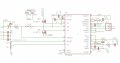
I'd like to build a DC/DC converter with the following characteristics:
-Vin: 15V to 10V
-Vout: 11V (if Vin is less than Vout then Vout should be equal to Vin)
-Ioutmax: 8A

I've tried designing a board with LT3840 to output 12V/20A as it says in the datasheet (problem: worked once, but never worked again)

i'm attaching the schematic
 

Attachments

Hi qwerty88!

I'm not sure, if my reply is already too late. At least it might help someone else, who is also struggling with getting the LT3840 to work properly.

The description of the problem was not very precise, but I will try to help and share my experience with the LT3840 up to now (i'm currently prototyping a board which uses LT3840).

The first problem I get from your schematic is a miscalculated shunt-resistance (R13): The average maximum differential sense voltage of 50mV yields on a 1.5mOhm resistor a maximum current of 50mV/1.5mOhm=33.33A! Maybe some circuit components were damaged, if such a high current output was reached. You should check on that. For a current limit of 8A you would need a shunt resistance of 6.25mOhm, but I don't think that this value is available. Instead you could use a 5mOhm resistor as shunt and use the ICTRL pin to program the current limit to a lower value of 8A. In your case a voltage of 0.8V has to be applied to ICTRL (maybe a resistor divider using INTVCCs 7.5V could help with that).
A second problem regarding the current control loop could be, that ICOMP pin is not connected to a resistor followed by a capacitor to GND. I think the current control loop won't work without being compensated by the resistor and capacitor (I used a 10kOhm resistor and a 470pF capacitor).
Also you could carefully read the LT3840s datasheet again, there is some helpful application hints.

A general problem of LT3840 could be not enough heat conduction of the exposed pad at the bottom of the IC: Assure that the exposed pad is properly soldered to a GND pad on your PCB, otherwise the IC will overheat and be damaged (this was the case during my prototyping phase). A way to solder the TSSOP-28 package by hand could be to extend your GND pad on your PCB far enough on the sides of the IC. In my case it was necessary to use a solder iron (on the extended GND pad) and a heat fan to solder it in properly. But after that it always stayed cool. If INTVCC pin does not rise up to 7.5V completely and the LT3840 is getting really hot, this may be a sign that the exposed pad is not soldered properly and the IC already overheated.

Maybe You will also experience a notable oscillation of your output voltage during light loads (<500mA for example). I don't know if something went wrong with my design, but puls-skipping-mode helped best to minimize this oscillation in combination with reducing the 1/(R*C) value of the resistor and capacitor at VC pin (20kOhm and 220nF in my case).
 
Status
Not open for further replies.
Top