Step Up/down converter working

Status
Not open for further replies.

Thread Starter

Electronic_Maniac

Joined Oct 26, 2017
253
Hi all,

I am told to use this IC to step up voltage from +5V to +23V. https://www.onsemi.com/pub/Collateral/NCP3063-D.PDF

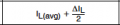
This datasheet has similar application circuits which are similar to my requirements. But I would like to understand the inner working of the IC and then derive my own application circuit. Can someone tell me what purpose do the SWC and SWE pins serve and how does the darlington pair help to boost clearly.
In the operating description section, it is given as the operating is similar to a capacitor charge pump circuit. Can someone explain that also?
What care should I Take while designing?
I don't understand how to start and where to start.
Please help.

Thanks.
 

OBW0549

Joined Mar 2, 2015
3,566
If you don't understand this:

Can someone tell me what purpose do the SWC and SWE pins serve and how does the darlington pair help to boost clearly.
or this:

I don't understand how to start and where to start.
then I don't recommend you try doing this:

But I would like to understand the inner working of the IC and then derive my own application circuit.
So,

What care should I Take while designing?
Take EXTREME care. The design of switching regulators, whether buck, boost, buck/boost or flyback, is definitely NOT something a beginner should attempt, lest he end up confused and discouraged.

Instead, build one or more of the application circuits shown on the data sheet to see how they work, and meanwhile read up on how switching regulators function. The two attached Linear Technology application notes would be a good place to start.
 

Attachments

Last edited:

DickCappels

Joined Aug 21, 2008
10,661
SWC =Collector of the output switch
SWE = Emitter of the output switch

Depending upon what you are doing with the chip, you may take the output from the collector or the emitter.

This is a version of the Motorola MC34063, the operation of which is described in Motorola's 1985 Application Note AN954, attached.

In a boost converter the Darlington is used switch voltage across the output inductor. When the output transistors switch off, the collapsing magnetic field in the inductor to cause current to continue to flow, but instead of going through the switch it goes through a diode typically: to charge an output capacitor.

To get started, read the excellent references mentioned in posts #2, 3, and 4 to learn the fundamentals. Then you can study the application note specific to this IC (attached below).

It is a good idea to start with the recommended circuits, because then you can use the MC34063 calculator tools. <=There are several on the web.
 

Attachments

ebp

Joined Feb 8, 2018
2,332
These parts are all derivatives of the Fairchild µA78S40 which was designed somewhere around 40 years ago. They are inexpensive and quite easy to use, but generally perform rather poorly in terms of efficiency relative to more modern parts (that Darlington switch is the problem in terms of efficiency).

The datasheet for the ON part and other ap notes mention it, but it is important to realize that these parts work quite differently from the great majority of switcher controllers in terms of the feedback method. They still use pulse width modulation but the control technique is "hysteritic" - a certain amount of ripple voltage at an unstable frequency is "forced" on the output. It is a method that gets around difficult issues of frequency compensation that exist for the more common types, but it means that the pulse width is always changing and looks unstable even with a fixed input voltage and fixed load. Figure 14 of the NCP3063 datasheet shows this.

www.ti.com/lit/an/snva026b/snva026b.pdf

Also note that it is quite common to find the inverting configuration called "buck-boost" but this is wrong. It is neither buck nor boost, but a completely distinct topology that is actually functionally identical to a flyback converter except that the inductor uses a single winding instead of two. The TI (originally National Semiconductor) ap note, above, describes the operation of the each of the three basic topologies well. There are true buck-boost controllers available, but the circuit is much more complex.
 

Thread Starter

Electronic_Maniac

Joined Oct 26, 2017
253
SWC =Collector of the output switch
SWE = Emitter of the output switch

Depending upon what you are doing with the chip, you may take the output from the collector or the emitter.

This is a version of the Motorola MC34063, the operation of which is described in Motorola's 1985 Application Note AN954, attached.

In a boost converter the Darlington is used switch voltage across the output inductor. When the output transistors switch off, the collapsing magnetic field in the inductor to cause current to continue to flow, but instead of going through the switch it goes through a diode typically: to charge an output capacitor.

To get started, read the excellent references mentioned in posts #2, 3, and 4 to learn the fundamentals. Then you can study the application note specific to this IC (attached below).

It is a good idea to start with the recommended circuits, because then you can use the MC34063 calculator tools. <=There are several on the web.
I am using this as a boost converter. Input (7.5V-16.5V). Output 23V and load current 255mA.
How to find the peak current and Vswce parameter in the datasheet - NCV3063? The calculation formula is not given for Ipeak and Vswce.
I have started to design but stuck while calculating (Ton/Toff), please help. https://www.onsemi.com/pub/Collateral/NCP3063-D.PDF

Please help
 

Thread Starter

Electronic_Maniac

Joined Oct 26, 2017
253
Have you checked Figure 15 of the datasheet?
View attachment 168670

Better yet, you can save time and incidental errors by using an online calculator like this one.
https://www.electronicproducts.com/DC-DC_Circuit_Calculator.aspx
Yes. But when you check that table, there is no formula for finding the Vswce. Point 9 tell us to check the fig. 7,8,9,10. But I dont know how to check and get data from that graph. Can you please help with this?

And one more doubt I have. Fig.25 is similar to my circuit. Can you explain me one current cycle for on and off states. How does the current flow? What is its path?
When SWE goes High, MOSFET get turned on and current will flow from Vcc to ground through L1 inductor and Q1 MOSFET.
But if SWE is high, current will flow from Vcc to SWC and then to SWE,right? So, current will not flow through L1 when SWE is high? It contradicts,right? Where am I going wrong in this?
 

DickCappels

Joined Aug 21, 2008
10,661
Yes. But when you check that table, there is no formula for finding the Vswce. Point 9 tell us to check the fig. 7,8,9,10. But I dont know how to check and get data from that graph. Can you please help with this?
(Some text removed for clarity)
Does it help to know that the collector voltage on the output switch is about 1 diode drop higher than the output voltage?

And one more doubt I have. Fig.25 is similar to my circuit. Can you explain me one current cycle for on and off states. How does the current flow? What is its path? (Some text removed for clarity)
upload_2019-1-26_0-25-35.png
This is a classic flyback (boost) converter. The drive signal from IC1 is buffered by IC2 and applied to the gate of Q1. During the time Q1 is on current through L1from the input power supply increases. When Q1 turns off the current through L1 continues to flow but through the D1, the output capacitors and the load rather than Q1.

For even more exciting reading, have a look at this:
https://en.wikipedia.org/wiki/Boost_converter
 

Thread Starter

Electronic_Maniac

Joined Oct 26, 2017
253
Does it help to know that the collector voltage on the output switch is about 1 diode drop higher than the output voltage?


View attachment 168684
This is a classic flyback (boost) converter. The drive signal from IC1 is buffered by IC2 and applied to the gate of Q1. During the time Q1 is on current through L1from the input power supply increases. When Q1 turns off the current through L1 continues to flow but through the D1, the output capacitors and the load rather than Q1.

For even more exciting reading, have a look at this:
https://en.wikipedia.org/wiki/Boost_converter
Thank you
 

Thread Starter

Electronic_Maniac

Joined Oct 26, 2017
253
Does it help to know that the collector voltage on the output switch is about 1 diode drop higher than the output voltage?


View attachment 168684
This is a classic flyback (boost) converter. The drive signal from IC1 is buffered by IC2 and applied to the gate of Q1. During the time Q1 is on current through L1from the input power supply increases. When Q1 turns off the current through L1 continues to flow but through the D1, the output capacitors and the load rather than Q1.

For even more exciting reading, have a look at this:
https://en.wikipedia.org/wiki/Boost_converter
Thank you very much. I understood. Can you please help me on how to calculate the Vswce? The two transistors on the outside of the IC helps in switching. The darlington switch at the inside of the IC does not help in switching. So, how can I calculate the Vswce in this case? The formula is not mentioned in the datasheet. My input voltage range is 7.5V to 16.5V and output load current is 255mA. Can you please give me a simple hint or a way of approach in a way that I can understand? Please. And what does the Ton/toff parameter mean? Is it the duty cycle parameter? Please help
 

DickCappels

Joined Aug 21, 2008
10,661
It is not the right way to calculate it but it is a good way to know whether you should expect trouble.

To calculate it you need to subtract the IR drop across R1. The current will be very close to Ipk(switch) = upload_2019-1-28_11-34-28.pngor otherwise as programmed with the Ipk voltage on pin 2 in conjunction with R1.
 

Attachments

Status
Not open for further replies.
Top