Standard BJT Amplifier vs Cascode Amplifier

Thread Starter

dcbingaman

Joined Jun 30, 2021
1,065
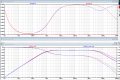
I was experimenting around with standard common emitter BJT amplifiers vs the same amplifier using cascode configuration. I have noticed the original amplifier has better frequency response than the one with cascode. Just wondering what is wrong. Attached is the LTSpice.

1632852242741.png

I have noticed no improvement and in fact a loss of gain on the same circuit cascode. The sim shows the standard amplifier has better frequency response. The opposite of what I expected?
 

Attachments

Thread Starter

dcbingaman

Joined Jun 30, 2021
1,065
There does appear to be some 'benefit' if the input signal impedance is 'high'. Here I got a benefit on this one with AC gain at 100 per stage cascode loading is less. That seems to make sense.

1632861680888.png
R12 and R13 acting as high impedance inputs to amplifier. At 10Mhz Cascode has better gain. I sure don't see any advantage with cascode. I could just have easily used an emitter follower to decrease the the signal impedance to the first stage.
What is all this talk about the cascode being 'superior' at higher frequencies? I sure don't see any.
 

Thread Starter

dcbingaman

Joined Jun 30, 2021
1,065
I don't AC gain of 100. Don't evaluate these amplifiers until they are working right.
Fair enough. Go back to the first circuit I presented with a gain of 10 and reduce the input frequency to say 100Khz. The output from the CE is as to be expected (slightly less than 10 due to little re) and the cascode looks exactly the same at that frequency. As you increase the frequency from 100K to 10Meg the gain of the CE is better than that of the cascode.
 
Last edited:

Thread Starter

dcbingaman

Joined Jun 30, 2021
1,065
I don't AC gain of 100. Don't evaluate these amplifiers until they are working right.
It is close to 100 if you reduce the input impedances that I have there to simulate the source and reduce the frequency from 10Mhz to 100Khz. That is just make R12 and R13 0 ohms. One of the supposed benefits is cascode has higher input impedance. I don't consider that a very large benefit.
 

ronsimpson

Joined Oct 7, 2019
3,037
One of the supposed benefits is cascode has higher input impedance.
I don't think so. Both circuits have the same Emitter resistor and the same transistor Bata. So the input impedance should be the same.

The output transistor has less Miller effect in the Cascode.
 

Thread Starter

dcbingaman

Joined Jun 30, 2021
1,065
I don't think so. Both circuits have the same Emitter resistor and the same transistor Bata. So the input impedance should be the same.

The output transistor has less Miller effect in the Cascode.
If you look at the current in (C1) at 10Mhz for the CE it is 70uA(pk) for the Cascode (C2) it is 50uA(pk). Thus the cascode has higher input impedance than the CE. The way it was explained to me:
For CE the base to collector capacitance is the same as a capacitor going from the base to ground and multiplied by the gain of the circuit. So if a capacitance of say 10pF is from base to collector it ends up 'looking' like a 10pF*(1+|circuit gain|) say -10 or 110pF from base to ground. Because the Cascode has Q3 collector voltage fairly constant you only pay for the 10pF base to collector that looks like 10pF base to ground for AC.
 
Last edited:

sparky 1

Joined Nov 3, 2018
756
I think but not certain, the equivalent model has been worked out for an ideal simulation with regard to miller effect as the frequency increases. I believe it is easier to visualize the capacitive field around 2 parallel NPN transistors with using the equivalent model however the board and layout should be concidered in it's role in asking such a question.

https://engineering.purdue.edu/wcch...ce255Lecture_26_April26_Miller_Effect_Etc.pdf
 

ronsimpson

Joined Oct 7, 2019
3,037
Q1 has a capacitor inside from B to C. At high frequency current flows from C to B. Time constant is C & Base impedance. This makes a low pass filter. Because the gain is 10 the effect of the capacitor is 10X.
Q2 also has a B-C capacitor. Its current does not pass into the Base but into C3. So there is no slow down effect by B-C capacitance and Base impedance.
Q3 also has a B-C capacitor. There is no signal at Q3C and Q2E. So there is almost no current in this capacitor. The formula for how much the Miller cap effects the high frequencies includes the gain. Q3 voltage gain is about 0.
1632924693737.png
 

Thread Starter

dcbingaman

Joined Jun 30, 2021
1,065
Q1 has a capacitor inside from B to C. At high frequency current flows from C to B. Time constant is C & Base impedance. This makes a low pass filter. Because the gain is 10 the effect of the capacitor is 10X.
Q2 also has a B-C capacitor. Its current does not pass into the Base but into C3. So there is no slow down effect by B-C capacitance and Base impedance.
Q3 also has a B-C capacitor. There is no signal at Q3C and Q2E. So there is almost no current in this capacitor. The formula for how much the Miller cap effects the high frequencies includes the gain. Q3 voltage gain is about 0.
View attachment 249080
Excellent description of what is going on. Thanks.
 

ronsimpson

Joined Oct 7, 2019
3,037
If you want a fast amplifier:
The gain is best when running near 10mA of collector current.
1632952335564.png
When designing for speed, all the capacitors must be charged up/down by current. So running high collector current helps charge the capacitors. So keep the collector current high.

In the data sheet: The 2N3904, with 10mA of current, 20 Volts will have a gain of 1 at 300MHz, 10 at 30mhz, 100 at 3mhz. I usually keep the gain of each stage down. Cascode amplifiers, that I build, go unstable if the gain gets too high. (above 20) I often keep the gain at 10 per stage. Using the 2N3904 with a gain of 10, 30mhz is all you will get.
1632952568654.png
Another thing to think about is capacitance verses voltage. From the graph the output capacitance is 1.4pF at 30 volts and 2.8pF at 1V. So keep some C-E voltage. This transistor is not bad but some high voltage parts get real slow if they see less than 5V across the transistor.
1632952973421.png
 
The basic idea behind the cascode is to limit the travel of the collector in the 1st device such that the Miller effect does not have too much effect on the input signal allowing a higher Zin and a better/higher freq response - this was first used on valves to get higher freq performance - any ckt that allows the collector to move too far is a wee way away from a true cascode ...
 

Thread Starter

dcbingaman

Joined Jun 30, 2021
1,065
If you want a fast amplifier:
The gain is best when running near 10mA of collector current.
View attachment 249117
When designing for speed, all the capacitors must be charged up/down by current. So running high collector current helps charge the capacitors. So keep the collector current high.

In the data sheet: The 2N3904, with 10mA of current, 20 Volts will have a gain of 1 at 300MHz, 10 at 30mhz, 100 at 3mhz. I usually keep the gain of each stage down. Cascode amplifiers, that I build, go unstable if the gain gets too high. (above 20) I often keep the gain at 10 per stage. Using the 2N3904 with a gain of 10, 30mhz is all you will get.
View attachment 249118
Another thing to think about is capacitance verses voltage. From the graph the output capacitance is 1.4pF at 30 volts and 2.8pF at 1V. So keep some C-E voltage. This transistor is not bad but some high voltage parts get real slow if they see less than 5V across the transistor.
View attachment 249119
Thanks for the advice! Appreciate it :)
 
Top