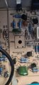
Hi Kiss, Overnight I was thinking about the control of quiescent current and if a fault in that area had caused the initial fault. If that was the cause then when we find the faulty component (Probably Q40, Q37, Q34 or Q36.) in the negative part of the signal path if we just replace it the amplifier will just try to destroy itself again. I think the circuit around Q29 controls the quiescent current. It seems to control the voltage between the bases of Q23 and Q40. If we consider Q40, Q37,Q34 and Q36 as a 4 stage emitter follower then the total voltage drop across their base emitter junctions will be between about 2.4 and 2.8 volts. so I would expect the voltage between the bases of Q23 and Q40 to be between about 4.8 and 5.6 volts. I will have to try to work out a way to check the circuit around Q29 before replacing the faulty component in the signal path. It is an interesting design as the voltage gain is provided by the long tail pairs at the input and the current gain by a 4 stage emitter follower at the output. Thanks for your comments. I had only started to think about this potential problem overnight.
Pete,
When you are checking the waveforms that I requested can you also measure the DC voltage between the base of Q23 and Q40.
The voltage between the Q24(C) and Q29(E) is the bias regulator. It should change with PR2.
For initial troubleshooting, you can see of the regulator is working and/or you can make it zero by shorting Q24(C) to Q29(E).
I have the luxury of a variac. Signal applied is always good and monitoring the Q24(C) and Q29(E) differential voltage.
It will be 2*n*Vbe depending on the amp. e.g. close to ~1.4, 2.8, 3.2, 4.8 V etc.
Basically with the voltage at minimum, you'll get cross-over distortion. It's also your bias adjustment when your monitoring DC current in any emitter resistor(voltage across). What I would normally do, if I didn't know the value of the bias current,+
is make slight adjustments in PR2 and monitor the differential voltage across Q24(C) and Q29(E) and monitor the heat sink temperature. You don't want temperature to climb after idling with no signal for about 20 minutes at least.
If PR2 doesn;t vary the voltage, you can force it to be zero by shorting Q24(C) to Q29(E).
ALWAYS check any low value resistors in the output stage.
Q17 and Q18 need to be matched in Hfe and so do Q19 and Q20. i.e. Within 10%.
I don't necessarily believe 500W with +-50V supplies unless it's like into 2 ohms.
The only time I use a load is for the final test. That's when Hfe matching would reveal itself.
I built a modified version of The Leach Amp and it took me a while to figure out I made a mirror image PCB. Switching the NPN's for PNP's and modifying the bias regulator, I was able to use the boards. The design was so symetrical.
Power amps are not necessarily good projects to learn on. All of the parts have to work.
An aside:
I bought a Harrison Labs (HP) Power 0-32 V "selectable" Supply. It used a bunch of paralleled transistors. When I added a headlamp as a load, the transistors started to short. The reason for selectable is because you selected a tap on the transformer.
I think the bias voltage is the voltage between Q24 collector and Q29 emitter. (Not collector.)
I don't think PR2 is fitted. (I am assuming NF stands for not fitted.) If I am right about this then there is only one pair of output transistors fitted.
I agree with the need to match the hfe of the output transistors.
I also agree that it is unlikely to supply 500 watts output. (Not even 250 per channel If the 500 watts is the total for two channels.)
I very much agree that the TS should have started to learn about electronics with much simpler and lower power circuits.
I don't think PR2 is fitted. (I am assuming NF stands for not fitted.) If I am right about this then there is only one pair of output transistors fitted.
There is nothing in the picture to give sense of scale so I can only make a guess at there rating. I I assume they are 0.5 watt rating then use 4 connected as two pairs connected in parallel connected in series. (This will make 10 ohms with 2 watts rating.)
They will probably get hot particularly when we fix the fault.
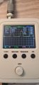
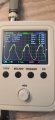
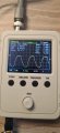
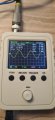
Here is the sinewave with the resistors across the output, not sure if it helps but this was taken from T9 and T34, there is nothing from the speakon jack with the resistors on it
Vmax is near zero, so one side isn't conducting. I think that's what I'm looking at.
Generally, you have to watch the small values resistors. They either increase in value or open.
You need to confirm the bias regulator is working.
You need to confirm if that potentiometer (N.F.) is fitted.
Vmax is near zero, so one side isn't conducting. I think that's what I'm looking at.
Generally, you have to watch the small values resistors. They either increase in value or open.
You need to confirm the bias regulator is working.
You need to confirm if that potentiometer (N.F.) is fitted.
Thinking back, all the main outputs were replaced in one go as i thought it better to replace them all, however somewhere along the way i blew Q28 and replaced it with an old good one, am i right in thinking this is on the + side of the circuit ? , and is it possible all the others i replaced are not suitable ? And the reason i only have the + half of the sine wave
Can you check the waveform with the scope probe tip on T10 and it's ground lead on T9. Also what was the voltage reading that I requested in post 103 ? (Q23 base and Q40 base.)
I think Q36 has an open circuit base emitter junction.
Generally transistors short, leak or have gain issues. The small value resistors act as fuses, so it;s really important to look at those. Opens do happen.
The paralleled transistors generally have to be gain matched within about 10%. The emitter resstors help with the current sharing, but not enough. In this phase, you really don;t have to worry about it. At higher currents, that's when it matters. One transistor takes more of it's share, pops and takes out the other one.
You can match the gain without a transistor checker. You will look at the ratio of collector to base current, You'll need a couple of resistors and a power supply/battery,.
I'll let Les Lead, but I did repair amps professionally. I only did the hard ones on a part-time basis at home for a consumer repair shop.
the most unusual was an amp used for a disco. 5 shops refused to repair it. It was borrowed from a relative of the owner and it was a "repair-cost no object". Some of the components (metal film resistors) had melted on the PCB. The amp was an easy repair and, it too, got an engineering fix - thump suppression was added. The speaker output terminals were shorted with wire.
Another "hard repair" was a return to the shop multiple times for the same issue. Bad IC amplifier. Turns out the absolute maximum ratings of the IC were exceeded. That required an engineering fix as well.
The first few stages of a class AB amplifier are designed to provide voltage gain and phase splitting. The output stage generally provides current gain. You have this temperature compensated bias regulator that makes the outputs conduct "a little" so there is no cross-over distortion. e.g. a gap between the + and - sides of the waveform. Vbe varies with temperature, (-10mV/deg K, I think) so it's wise to have it bolted to the heat sink.
There is an RF filter at the input and a Zobel (L/R) network on the speaker. Finally, there overall negative feedback which also rolls off the frequency response of the amplifier. 20-20kHz is normal.
My amp: un-rolled off DC-800kHz. Rolled off 0.5Hz to 40 kHz.
A good amp needs to be able to push a lot of current through the speaker resonance frequency.
You don't see very many amplifiers with differential inputs. There is always or should be some larger capacitance near the output stage. e.g 100 uF.
"Common" is really the negative post of the speaker.
Then, there is always the possibility ground loops.
Professional voltage levels are more like the tape in/out levels of a pre-amp. The inputs and are balanced. i.e differential.
Hi kiss, It sound like you have more experience than me at fixing amplifiers so it would be better for you to take over.
Just a few comments. There is only a single pair of transistors in the output stage. Q35 and Q27 are not fitted,
I looked up the spec on this amplifier and it is rated at 125 watts per channel.
I'm just under way to much stress right now to be of any use. Long-distance troubleshooting is really tough.
I still want to know if the bias regulator is working? With the pot not fitted makes me wonder if the fixed parts are selected?
Like I said, I really learned the hard way. I made a mirror image of the Leach Amp board and the trouble-shooting to find that brought understanding to an unheard of level.
I screwed up too. The article secified a 3A 70V CT transformer and I used 4x35V @ 3A. +-50VDC rails. That isn;t good enough, The article also mentioned driving electrostatic speakers, so current doesn't matter.
Listening to my amp and a McIntosh tube amp with the "Voice of the Theater" horn speakers yielded something very odd. The 7W valve amp sounded louder. It makes sense when you think about it.

 Facebook
 Google
 GitHub
 Linkedin