SR Latch Within an SR Latch?

iimagine

Joined Dec 20, 2010
512
It looks like the 10nF capacitor will keep the reset signal to the transistors bases low after the set PB is released, which would mean everything is reset.
It would seem like you need a delay on the set to the PNP, not the reset (such as a cap from the PNP base to ground).
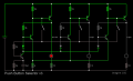
Yes, the 10nF capacitor will keep the reset signal to the transistors bases low after the set PB is released for a bit, but the selected FF will remains set because the instant the PB is pressed, its already turned on and latched thus continues to provides enough base current to keep it on. The purpose of the 10nF is to bypass the 100k emitter resistor so that when a PB is pressed, the reset transistor turns on hard for a split second to ensure the cutting off to all NPN transistors base
EDIT: What did you use to make it black and white? :D
 

crutschow

Joined Mar 14, 2008
38,503
What did you use to make it black and white?
Used an old program I have called Corel Photo-paint.
I first inverted the colors (make them complementary), which also converts the black background to white, and then I converted it to 1-bit black and white, which removed any color.
 

crutschow

Joined Mar 14, 2008
38,503
iimagine, here's the LTspice simulation of your circuit modified.

When you added the common emitter resistor to the circuit, I suspected that could be sufficient to create the proper switching action without the addition of the reset transistor and diodes.
The simulation shows that it does indeed work without them, as you can see the LEDs sequentially turn on in response to their respective pushbutton operation.
The common emitter resistor was a smart addition as it doesn't allow more than one LED to be on at a time.
This makes one of the simpler Radio PB circuits I've seen.
The circuit also doesn't draw any significant current from the latches not energized.

(Nit: Why do your schematics have no part numbers. It makes it difficult to talk about the circuit.)

1585296248341.png
 
Last edited:

iimagine

Joined Dec 20, 2010
512
iimagine, here's the LTspice simulation of your circuit modified.
Ah nice! Honestly, when I added that common emitter resistor, the same thought occurred to me that the reset transistor was not needed too.
Yep, cant be simpler then this!
As for why my circuit dont have any part numbers.... one word - 'laziness'
 

MisterBill2

Joined Jan 23, 2018
27,505
iimagine, here's the LTspice simulation of your circuit modified.

When you added the common emitter resistor to the circuit, I suspected that could be sufficient to create the proper switching action without the addition of the reset transistor and diodes.
The simulation shows that it does indeed work without them, as you can see the LEDs sequentially turn on in response to their respective pushbutton operation.
The common emitter resistor was a smart addition as it doesn't allow more than one LED to be on at a time.
This makes one of the simpler Radio PB circuits I've seen.
The circuit also doesn't draw any significant current from the latches not energized.

(Nit: Why do your schematics have no part numbers. It makes it difficult to talk about the circuit.)

View attachment 202530
This circuit, and the preceding versions, offer a fundamentally different mode of operation, in that each output has a different button to select it. That could easily be duplicated with an array of relays and some diodes. Or possibly the requirements have changed and I missed that. There has certainly been a bit of wandering from the original topic.
 

crutschow

Joined Mar 14, 2008
38,503
This circuit, and the preceding versions, offer a fundamentally different mode of operation, in that each output has a different button to select it.
Which is what the TS wanted.
I press button A, LED A turns on and all other LED's turn off, Button B, LED B turns on and all other LEDs off, and So on into infinity
That could easily be duplicated with an array of relays and some diodes.
Why would you want to use expensive and less reliable relays in place of cheap transistors?
 

MisterBill2

Joined Jan 23, 2018
27,505
Which is what the TS wanted.

Why would you want to use expensive and less reliable relays in place of cheap transistors?
No particular reason to use relays, I was just saying that the logic could be fairly simple. Unfortunately the two ring counter circuits in my reference book use SCR devices, 2N1595 types, not at all what the TS wants to use. I will look a bit more. One alternative is a string of 2 transistor flip-flops and some decoding logic. Classic from about 1970. Another circuit uses complementary pairs of transistors, PNP and NPN, perhaps 2n3904 and 2N3906, and 3 resistors, 1 diode, and a capacitor between stages. Also the circuit shows one more NPN as the driver, but that could also be the pushbutton. That circuit is on page 187 of the 1974 edition of "Guidebook of Electronic Circuits", by John Markus, printed by McGraw-Hill, 1974. There is an even simpler version using 4-layer diodes, (M4L3050 series, Motorola), on page 185, but I have no idea where you could get them or even how they work.
 
Top