Sr flip flop question

Thread Starter

Muhammad Salman Ali

Joined Apr 6, 2019
11
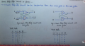
Hello! I am confused in a question I found on youtube. I have uploaded the screen shots.
He told that with respect to S and R we have to write the change from Q to Q+( next state). But I am not getting it. How he wrote Q+ states? Thanks!
 

Attachments

Thread Starter

Muhammad Salman Ali

Joined Apr 6, 2019
11
Is he considering that when S=1 , we have to set the circuit i.e on Q , 1 will be stored and the circuit will be set and vice versa? But this is a nand latch right? S is above R and infront of S there is Q. So it is a nand latch in which when S=1 Q is 0.
 

crutschow

Joined Mar 14, 2008
34,201
Normally the S(et) input asynchronously sets the Q output to the 1 state, and the R(eset) input sest the Q output to the 0 state, independent of what else is happening.
 

WBahn

Joined Mar 31, 2012
29,932
It's hard to tell exactly what you have with this part because normally an SR latch doesn't have a clock input. What, exactly, is the behavior of that part as you've been given it?
 

WBahn

Joined Mar 31, 2012
29,932
Normally the S(et) input asynchronously sets the Q output to the 1 state, and the R(eset) input sest the Q output to the 0 state, independent of what else is happening.
Not quite independent since if they are both asserted at the same time this behavior doesn't hold.

There's also the question of just what the edge-triggered clock input to that part is doing.
 

WBahn

Joined Mar 31, 2012
29,932
Is he considering that when S=1 , we have to set the circuit i.e on Q , 1 will be stored and the circuit will be set and vice versa? But this is a nand latch right? S is above R and infront of S there is Q. So it is a nand latch in which when S=1 Q is 0.
This makes very little sense to me. What do you mean by "S is above R and infront of S there is Q"? Are you talking about where the labels are shown on the diagram? If so, that has no bearing whatsoever -- you can put the labels wherever it is convenient.

The implication (leaving this clock input aside for the moment) is that S is active HI (otherwise it would be called /S -- or some other way of indicating that it is asserted when that input is LO). Assuming the latch is either cross-coupled NAND gates or cross-coupled NOT gates, which would that mean?

But you shouldn't need to know what is inside the part, just how it behaves.

Probably the best way to see what is going on it to draw a timing diagram that reflects the delays through each part. In particular, the delay through that inverter, because that will let you see the relationship between the signals at the S and R inputs.
 

Thread Starter

Muhammad Salman Ali

Joined Apr 6, 2019
11
This makes very little sense to me. What do you mean by "S is above R and infront of S there is Q"? Are you talking about where the labels are shown on the diagram? If so, that has no bearing whatsoever -- you can put the labels wherever it is convenient.
.
I saw a video in which he said that there are two types of latches nand latch and nor latch! In nand latch Q is infront of S while in not R is infront of Q. both the tables give different outputs.I have uploaded the screenshot!
 

Attachments

WBahn

Joined Mar 31, 2012
29,932
I saw a video in which he said that there are two types of latches nand latch and nor latch! In nand latch Q is infront of S while in not R is infront of Q. both the tables give different outputs.I have uploaded the screenshot!
What does it mean for Q to be in front of S or for R to be in front of Q?

I have no idea what it means for an input to be in front of an output, nor what it means for an output to be in front of an input.

Yes, you can make a set-reset latch out of either two NOR gates or two NAND gates. But where you put the labels on a part that represents them is completely arbitrary.

If that screen shot is from some video, I suggest you find a different video.

A NAND-based FF has active-LO inputs, generally called /S and /R (or S-bar and R-bar or S' and R' or S with in overbar symbol and R with an overbar symbol). When the /S input is LO and the /R input is HI, the Q output is HI and the /Q output is LO. When the /S input s HI and the /R input is LO, the Q output is LO and the /Q output is HI. When both inputs are HI the output is whatever it was before with one output HI and the other LO. When both inputs are LO, then both outputs are HI. If both inputs are subsequently taken LO at the same time, the result is indeterminate -- one output will be HI and the other will be LO, but there is no telling which will be which.

A NOR-based FF has analogous behavior except that the inputs are active-HI. If both inputs are asserted at the same time, both outputs will be HI.

I still have no idea what that clock input is going into your flip flop symbol. Do you?
 

WBahn

Joined Mar 31, 2012
29,932
Its behaving like t flip flop!
You are saying that you have been told that a symbol with an S input, an R input, a clock input, and two outputs behaves like a T Flip Flop? Does that make any sense to you?

Forget about the overall circuit in the problem. You can't possibly solve that problem until you clearly understand what that part is and how it behaves.
 

WBahn

Joined Mar 31, 2012
29,932
Then the first value of Q+(the next state) should have been 1 because S=0, R=1 so it will be reset! Isn't it so?
I have no idea. It is pointless for me to even consider this until you can describe what that part -- the box with the S and R and the unnamed rising-edge sensitive inputs and the Q and /Q output -- does. It is NOT an SR latch because SR latches, of EITHER flavor, do NOT have a third edge-sensitive input.
 

Thread Starter

Muhammad Salman Ali

Joined Apr 6, 2019
11
I have no idea. It is pointless for me to even consider this until you can describe what that part -- the box with the S and R and the unnamed rising-edge sensitive inputs and the Q and /Q output -- does. It is NOT an SR latch because SR latches, of EITHER flavor, do NOT have a third edge-sensitive input.
The guy didn't talk about clock in the video. Lets just forget that! Now do you think that first value of Q+ is wrong according to sr.
 

WBahn

Joined Mar 31, 2012
29,932
The guy didn't talk about clock in the video. Lets just forget that! Now do you think that first value of Q+ is wrong according to sr.
The issue isn't whether some guy in some video talked about a clock. The issue is whether the circuit in the problem you are trying to solve has a clock. Does it? It makes a HUGE difference.

If we forget about the clock, then assume the Q output is initially 0 and the x input is also initially zero. Now take the x input to 1 and just leave it there. What does the circuit do? Draw a timing diagram.
 

Thread Starter

Muhammad Salman Ali

Joined Apr 6, 2019
11
The issue isn't whether some guy in some video talked about a clock. The issue is whether the circuit in the problem you are trying to solve has a clock. Does it? It makes a HUGE difference.

If we forget about the clock, then assume the Q output is initially 0 and the x input is also initially zero. Now take the x input to 1 and just leave it there. What does the circuit do? Draw a timing diagram.
So what are you saying is that the question is wrong. Right?
 

WBahn

Joined Mar 31, 2012
29,932
So what are you saying is that the question is wrong. Right?
I don't know if the question is wrong because I can't get you to confirm what the question is.

Does the circuit, as given in the actual problem, have a clock input as shown in your hand-drawn diagram? Yes... or... No?

If the circuit uses a clocked RS flip flop, then it will behave very differently than a circuit that uses an unclocked one. In either case, you can't just choose to ignore the circuit as given and treat it as something else.
 

MrChips

Joined Oct 2, 2009
30,621
Analyze what would happen if it were a level sensitive S-R flop-flop that required no clock.
This would lead me to assume that the clock plays an important part of this circuit.
 

RBR1317

Joined Nov 13, 2010
713
I think it is just a trick question where the FF is not being used as a FF, but is wired such that Q=Z' so all that needs to be done is to find the expression for Z.
 

WBahn

Joined Mar 31, 2012
29,932
I have taken the screenshot with high quality now! The question is clearly visible. This question is from gate exam.
So you have a gated SR flip flop. The important thing -- far more important than this question -- is do you understand how a gated SR flip flop behaves? Can you describe it?
 
Top