Square wave generator -HELP NEEDED PLZ-

Thread Starter

Mu86neer

Joined May 1, 2009
23
hi :confused:
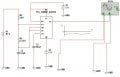
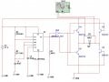
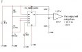
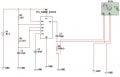
i've been trying to design a square wave generator on multisim using 555 timer (astable), and the problem is that the output appears to be oscillating on the positive portion of the graph ( either positive amplitude or zero). in fact, it has to be fluctuating in both sides to convert it to triangle later on.
THANK YOU FOR HELPING ME :)
 

Attachments

Last edited:

Thread Starter

Mu86neer

Joined May 1, 2009
23
well, i removed them and the problem is still there,,, there is only positive square amplitude ( how to make it oscillate in both positive and negative sides ? )
 

bertus

Joined Apr 5, 2008
22,270
Hello,

At what amplitude do you want the squarewave to go positive and negative?
Is there any power needed for this voltage?


Greetings,
Bertus
 

Thread Starter

Mu86neer

Joined May 1, 2009
23
its basically DC input which is converted into square waveform that has positive and negative amplitudes,,, multivibrators (astable) shows two states either positive max amplitude or zero.
thus, the question is how to make this circuit proceeds to the negative side,though its a square signal ..
 

beenthere

Joined Apr 20, 2004
15,819
Look at your circuit. The 555 is powered by +10 volts and ground. The output can only be 0 or +10 volts. A negative voltage does not exist in the circuit as it is.

For an output with positive and negative excursions, put + 5 volts to pins 8 & 4, and -5 to pin 1.
 

Thread Starter

Mu86neer

Joined May 1, 2009
23
Thank you very much for all the affords u put :)....
that was very helpful,,,
i designed it on multisim and i got some kind of irregular waveform of the output and then it suddenly stopped running,,, if u please could take alook at the two attached images, it'd be highly appreciated.
 

Attachments

aboamal

Joined May 29, 2008
14
hi
I have modified the circuit little bit to become more stable.

In this circuit you can change the frequency of the square wave through R1 and C1

Frequency=1/R1*C1

you can use timer 555 to produce pulses instead of NAND gate 4093.


SgtWookie

Joined Jul 17, 2007
22,230
aboamal,
I'm surprised that your simulation runs. For example, look at how much base current you're getting on Q5. A real-world 4093 wouldn't be able to source that much current, and have enough left over to charge C1 via R1 and get above the Schmitt trigger level.

As I mentioned in the other thread where you posted a similar H-bridge configuration, you need current limiting resistors on the bases of Q5 and Q6, and also on Q1 and Q2. The Q1/Q2 base resistors will do "double duty" as base resistors for Q3, Q4.
 

Thread Starter

Mu86neer

Joined May 1, 2009
23
I ADDED TWO 10 OHM RESISTORS TO THE SET OF 4 BJT and it really works now, i guess the reason was each couple of BJTs was shortened ,,!!
its shown on the attached image ..:)
there is another thing i'd like to tell you , which is i finished my circuit and it converts an input of DC to a Rectangular signal and then into Triangular Signal using 555Timer, Integrator and Differentiator connected in series.
 
Last edited:

Thread Starter

Mu86neer

Joined May 1, 2009
23
fabulous, its anther implementation of using comparator to swing the input value depending on the frequency of the Timer f = 1.44/[(R1+R2)*C]
i feel lucky ..lol
 

Thread Starter

Mu86neer

Joined May 1, 2009
23
Mu86neer,

To expand on what beenthere advised, review this attachment.
-----------
Hello
its so helpful,,@
it appears to be an Astable Multivibrator, and i expect its operating frequency to be f= 1.44/[(2.7+30)*1000*33*10^-9] =7.655 k Hz

the operating frequency must be taken into consideration specially when this 555Timer is synchronized with other OpAmp applications such as integrator circuits.

Thank you
 
Top