Splitter with BJT

Thread Starter

DaniKowa

Joined Sep 23, 2020
218
Hi guys!

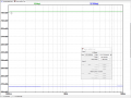
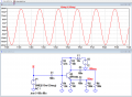
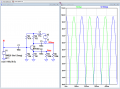
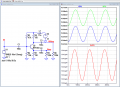
today I was thinking about a scheme of a splitter made with a BJT. In the two outputs the circuit allows to obtain two signals out of phase by 180 ° between them. Actually I found the scheme on the net and I replaced the BJT to get better performance between the two output phases. The problem is that on LTspice the two output signals are of the same amplitude while in the other software it does not happen. In fact on the first output I get 5.93mV while in the second I get 122uV. So the question is: Why do I get different results with the same pattern? And above all if there is an error what should I do to have two equal amplitudes on the two outputs? Thank you.

EDIT: I replaced the first image because the measured output values were missing.


Last edited:

Thread Starter

DaniKowa

Joined Sep 23, 2020
218
Hi Eric, thank's for your reply. I edited the first post by modifying the first image because the output measurements were missing. In fact, with LTspice I have not found any problem as you have confirmed. The problem I found in the other software that as now is visible I get 5.93mV on the PR5 and only 122uV on the PR6. The pattern is the same and I don't understand why.
 

ericgibbs

Joined Jan 29, 2010
21,442
hi Dan,
This is a re-run using the Vertical view, it shows an amplitude difference
E

Update: The possible problem is how well the transistor has been modelled in LTS.???

EG 1339.pngEG 1340.png
 
Last edited:

Papabravo

Joined Feb 24, 2006
22,082
Is the fact that the collector and emitter currents are not equal enough to convince you that the voltage waveforms cannot be equal. They could only be equal if there was zero base current.
 

ericgibbs

Joined Jan 29, 2010
21,442
hi Papa,
The initial query from the TS, is that LTS was not showing any difference, whereas another simulator showed the expected difference in the two outputs.
E
 

Papabravo

Joined Feb 24, 2006
22,082
hi Papa,
The initial query from the TS, is that LTS was not showing any difference, whereas another simulator showed the expected difference in the two outputs.
E
Right, but you demonstrated that it was not the case. I was commenting on the default assumption that with identical components they would automatically be the same. As you have noted you can adjust values of circuit components make them more equal within the tolerances of the components.
 

Thread Starter

DaniKowa

Joined Sep 23, 2020
218
OK , i seem to be solved. I have rebuild the circuit and now the results match. One last question, looking at the datasheet I saw that the VEBO is at 2Volt. Is it correct to replace R9 from 4k7 to 8k7? Here below schematic mentioned and DS.


Datasheet BFR183
 

ericgibbs

Joined Jan 29, 2010
21,442
hi Dan,
That is the same circuit you posted earlier, and it is still not giving equal amplitude output signals.
Your figures, in the two right side boxes of your posted results, show that they are different amplitudes.

As explained in post #8. [Look at a possible fix by using a 152R]
E
EG 1352.pngEG 1351.png
 

Thread Starter

DaniKowa

Joined Sep 23, 2020
218
Hi
hi Dan,
That is the same circuit you posted earlier, and it is still not giving equal amplitude output signals.
Your figures, in the two right side boxes of your posted results, show that they are different amplitudes.

As explained in post #8. [Look at a possible fix by using a 152R]
E
Yes is the same except the modify for resistor in the green circle below. From 4.7 to 8.7k.

mod.JPG
 

ericgibbs

Joined Jan 29, 2010
21,442
hi Dan,
There is still a small difference in LTS when a 8k7 is used.
Is this difference acceptable for your project.?

E
EG 1354.png
@DaniKowa
Added: log print out of PP values

EG 1353.png
 
Last edited:
Top