sourcing biggish electric dc gear motors

Thread Starter

Owen Nieuwenhuyse

Joined Jun 20, 2017
42
This is not directly electronics related, though I want to try and size a motor to the load, and a reasonable priced
controller, run by a microcontroller.
There seems to be a gap at 200W 12V 1500rpm 1 N-m, 16 amp or so. I want a cheap motor, not a high-dollar
industrial one. I am trying to get under 3 kgs also, as it is to fit on a motorcycle.
The cheapest I can get is $150 nz delivered, but it is massively overpowered and overweight.
I have a different query out on a limiting controller for this "beast" :) Any ideas, other sources?
I will look at the combat robots suppliers again, and see what they have.
It has to be around or under $us 110 including freight.
Brushed, permanent magnet , planetary geared is probably "it?"
 

shortbus

Joined Sep 30, 2009
10,049
Maybe telling what you are trying to do/make will get you better results. Many people come here thinking in only one direction on their projects. There are people on the forum that have many good ideas, if you explain at the beginning what it is you're trying to do, instead of making us guess.:) This statement is meant to discourage you, but to get you better ideas.
 

strantor

Joined Oct 3, 2010
6,875
Cannibalize an old garage sale 12v cordless drill. Motor and speed control in one package, plus a very capable gearbox if needed.
 

tcmtech

Joined Nov 4, 2013
2,867
Cannibalize an old garage sale 12v cordless drill. Motor and speed control in one package, plus a very capable gearbox if needed.
Same thoughts here. Cheap, mass produced and almost everyone has, or knows someone who has, a 12 volt or higher cordless drill that doesn't work due to a bad battery or such.
 

Thread Starter

Owen Nieuwenhuyse

Joined Jun 20, 2017
42
Same thoughts here. Cheap, mass produced and almost everyone has, or knows someone who has, a 12 volt or higher cordless drill that doesn't work due to a bad battery or such.
I had a look at Aliexpress, and the motors normally used in cordless drills are a bit small.
Dimension-wise, it needs to be about 50mm in diameter by 100mm long.
Those ones in drills are usually about 35mm diameter.
There are some small gear motors used as starter motors for motorbikes.
There is a lack of specs though. One for a 250cc or a 125cc motorcycle may do.
The one I am looking at is for an 1100 cc v-twin, and looks to be 4x too powerful.
The center section with the magnets in is about 70mm diameter by 75 mm long.
A 250cc motorbike is about 1/4 of that capacity, so it may do, if it has the right internal
step-down gearing.
 

tcmtech

Joined Nov 4, 2013
2,867
I had a look at Aliexpress, and the motors normally used in cordless drills are a bit small.
Dimension-wise, it needs to be about 50mm in diameter by 100mm long.
Those ones in drills are usually about 35mm diameter.
There are some small gear motors used as starter motors for motorbikes.
There is a lack of specs though. One for a 250cc or a 125cc motorcycle may do.
The one I am looking at is for an 1100 cc v-twin, and looks to be 4x too powerful.
The center section with the magnets in is about 70mm diameter by 75 mm long.
A 250cc motorbike is about 1/4 of that capacity, so it may do, if it has the right internal
step-down gearing.
What do the dimensions have to do with anything if the RPM and torque plus run time requirements are met? :confused:

Put it in a bigger chassis if you need it bigger. :rolleyes:
 

Thread Starter

Owen Nieuwenhuyse

Joined Jun 20, 2017
42
Maybe telling what you are trying to do/make will get you better results. Many people come here thinking in only one direction on their projects. There are people on the forum that have many good ideas, if you explain at the beginning what it is you're trying to do, instead of making us guess.:) This statement is meant to discourage you, but to get you better ideas.
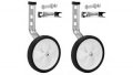
I want to run a ballscrew with 10mm lead, 280mm travel, to lift one motorcycle prop stand/jockey wheel
up and down. estimated load is 10 pounds, geared at 3:1. desired travel time = 1-2 seconds.

There are two separate prop stand wheels, 11 inches in diameter, pneumatic, to allow a load rating of
400 pounds per side. The motor is not expected to push against the maximum load.

The method has been chosen because of space constraints, plus the ballscrew and motor are
relatively cheap. The locking method is a disk brake on the motor axis. This allows locking in multiple
positions.
 

tcmtech

Joined Nov 4, 2013
2,867
I want to run a ballscrew with 10mm lead, 280mm travel, to lift one motorcycle prop stand/jockey wheel
up and down. estimated load is 10 pounds, geared at 3:1. desired travel time = 1-2 seconds.

There are two separate prop stand wheels, 11 inches in diameter, pneumatic, to allow a load rating of
400 pounds per side. The motor is not expected to push against the maximum load.

The method has been chosen because of space constraints, plus the ballscrew and motor are
relatively cheap. The locking method is a disk brake on the motor axis. This allows locking in multiple
positions.
If you are wanting a 1500 RPM motor then gearing it down 3:1 more that's pretty close to what most cordless drill motors do in low range. My Craftsman cordless drills are rated at ~ 450 RPM low range.

Also given their high reduction a disk brake would not be necessary either being the 10 or so pounds of force is not much of a mechanical advantage on a ball and screw linear actuator so it's extremely doubtful one would ever roll backwards when undr any amount of force a 10 mm shaft would hold up to.

Also if space and size are a constraint, again I don't follow why you would want a physically larger unit than what a cordless drill motor and gearbox makes up. :confused:

Lastly given the extremely short run times you could also runs lower voltage cordless drill motor on 12 volts without issue as well. a 7.2 or 9 volt would have no trouble at all with 12 volts for several second bursts.
 

GopherT

Joined Nov 23, 2012
8,009
I want to run a ballscrew with 10mm lead, 280mm travel, to lift one motorcycle prop stand/jockey wheel
up and down. estimated load is 10 pounds, geared at 3:1. desired travel time = 1-2 seconds.

There are two separate prop stand wheels, 11 inches in diameter, pneumatic, to allow a load rating of
400 pounds per side. The motor is not expected to push against the maximum load.

The method has been chosen because of space constraints, plus the ballscrew and motor are
relatively cheap. The locking method is a disk brake on the motor axis. This allows locking in multiple
positions.
I understand what you're looking for. Unfortunately, our neighborhood know-it-all will be rattling this cage from now until end of time. He just ignores the details that dont fit his reality (like travel time).

Ill take a look, i have an idea.
 

strantor

Joined Oct 3, 2010
6,875
I want to run a ballscrew with 10mm lead, 280mm travel, to lift one motorcycle prop stand/jockey wheel
up and down. estimated load is 10 pounds, geared at 3:1. desired travel time = 1-2 seconds.

There are two separate prop stand wheels, 11 inches in diameter, pneumatic, to allow a load rating of
400 pounds per side. The motor is not expected to push against the maximum load.

The method has been chosen because of space constraints, plus the ballscrew and motor are
relatively cheap. The locking method is a disk brake on the motor axis. This allows locking in multiple
positions.
This still sounds well within the capability of a cordless drill setup. If you're at all curious, why not just try it with an actual cordless drill (without disassembling it)? Just tighten the Chuck onto the drive end of the ballscrew and pull the trigger. I am willing to bet it fits your time and force requirements despite not being as physically large as you feel it should be. And with the intermittent duty, I don't see it ever burning up. I run my cordless drill to a dead stall on a regular basis and never had any issue.
 

tcmtech

Joined Nov 4, 2013
2,867
This still sounds well within the capability of a cordless drill setup. If you're at all curious, why not just try it with an actual cordless drill (without disassembling it)? Just tighten the Chuck onto the drive end of the ballscrew and pull the trigger. I am willing to bet it fits your time and force requirements despite not being as physically large as you feel it should be. And with the intermittent duty, I don't see it ever burning up. I run my cordless drill to a dead stall on a regular basis and never had any issue.
That's pretty much what I am thinking as well.

Going by the fairly standard 3 mm pitch a 10 mm ball track screw would have being turned at 1500 RPM would give it a linear travel rate of ~ 75 mm per second.

Then depending on the power of the motor I suspect it could easily produce at least 10's KG of push/pull force with even a basic drill that is good for around ~150 - 200 inch pounds / 17 - 23 N-M of rated torque which is about mid line torque range for a common 12 volt cordless drill and that's going by the high speed range torque ratings from the link below.

At the low speed torque ratings that would put it at 30+ KG of push/pull capability.

https://www.protoolreviews.com/buying-guides/best-12v-cordless-drill-roundup/25102/

http://www.zappautomation.co.uk/ind...ews/miniature-ballscrews-6-12mm-diameter.html

The bigger issue I have is trying to support up to 400 pounds of force with a 10 mm diameter threaded rod at a ~280 mm extension span. Unless those are some high strength screws that pushing the limits of how much compressional forces I would would put on a shaft that small on that span.

I believe they would hold it but given the slightest bit of bend and they will have a very high probability of buckling.
 
Last edited:

Thread Starter

Owen Nieuwenhuyse

Joined Jun 20, 2017
42
If you are wanting a 1500 RPM motor then gearing it down 3:1 more that's pretty close to what most cordless drill motors do in low range. My Craftsman cordless drills are rated at ~ 450 RPM low range.

Also given their high reduction a disk brake would not be necessary either being the 10 or so pounds of force is not much of a mechanical advantage on a ball and screw linear actuator so it's extremely doubtful one would ever roll backwards when undr any amount of force a 10 mm shaft would hold up to.

Also if space and size are a constraint, again I don't follow why you would want a physically larger unit than what a cordless drill motor and gearbox makes up. :confused:

Lastly given the extremely short run times you could also runs lower voltage cordless drill motor on 12 volts without issue as well. a 7.2 or 9 volt would have no trouble at all with 12 volts for several second bursts.
Torque and speed requirements are quite high. I want drop action sort of "instant", raise in 1-2 seconds.
I have found a good motor/gearbox combo at the RobotShop, thanks. I am also looking at rotary encoders.
http://www.robotshop.com/en/rs-775-motor-7000rpm-12v-7613oz-in.html
http://www.robotshop.com/en/banebots-p60-gearbox-15-shaft-rs-700-mount-41-no-grease.html
The space requirements mean that I have to use a linear actuator and cranks/levers/links,
I can't get a big 2-stage belt reduction drive in easily. possibly I could get a rotary final stage in there,
but the ballscrew is quite cheap.
There is a 1200 lbs push-back on the screw nut. I wasn't sure it would stay put. Any pivot bearing axles I use would be around 20mm + to suit. (3/4 inch) I will check loads and sizes.
A 20mm ballscrew has enough static load capacity. I have to design a carrier/pivot assembly for the
nut with ganged thrust bearings and ballraces. thrust race ID will be about 30mm, so they should be big
enough.
Next, I will be back to find out how to drive the motor controllers, and the math for positioning control
and feedback. Speeds are a bit high to let things slam into end buffers.
 

tcmtech

Joined Nov 4, 2013
2,867
Torque and speed requirements are quite high. I want drop action sort of "instant", raise in 1-2 seconds.
I have found a good motor/gearbox combo at the RobotShop, thanks. I am also looking at rotary encoders.
http://www.robotshop.com/en/rs-775-motor-7000rpm-12v-7613oz-in.html
http://www.robotshop.com/en/banebots-p60-gearbox-15-shaft-rs-700-mount-41-no-grease.html
The space requirements mean that I have to use a linear actuator and cranks/levers/links,
I can't get a big 2-stage belt reduction drive in easily. possibly I could get a rotary final stage in there,
but the ballscrew is quite cheap.
There is a 1200 lbs push-back on the screw nut. I wasn't sure it would stay put. Any pivot bearing axles I use would be around 20mm + to suit. (3/4 inch) I will check loads and sizes.
A 20mm ballscrew has enough static load capacity. I have to design a carrier/pivot assembly for the
nut with ganged thrust bearings and ballraces. thrust race ID will be about 30mm, so they should be big
enough.
Next, I will be back to find out how to drive the motor controllers, and the math for positioning control
and feedback. Speeds are a bit high to let things slam into end buffers.
The ball and screw type linear actuator with either a direct or inline planetary reduction will be the most compact but given the speeds, peak forces and input electrical powers involved the numbers aren't adding up well.

The 1200 pound peak pushing force is way past what a 10 mm shaft will safely hold up to at nearly a foot of extension but t 20 mm would be fine at that.

The next issue is realistic travel times and the motor speeds and RPM to achieve them.
Depending on thread pitch and masses to be moved you are looking at electrical input powers that will likely be well past 200 watts and likely closer to your idea of using a small starter motor that draws 50+ amps on activation but with that you have the rotational inertia to stop at the end of travel each way to deal with which with a disk brake you have some control but still precision repeatable stopping will not be all that fine.

I believe it could be built but not likely for the prices you are thinking unless you can get most everything as cheap surplus components and build it all yourself. There is just too much secondary aspects of the design to have to deal with beyond just spinning a shaft back and forth to make something move up and down.

Also if this is a prop wheel set for a motorcycle throwing a 10 pound mass up and down nearly a foot in 1 - 2 seconds is a fair amount of other inertial force to deal with that will be going against the main center of gravity of the bike itself.

Then there is the bigger issue of why you need it.
I have no clue but at the moment I am envisioning a sort of home brew anti tip-over system for a larger bike that is possibly heavier than its rider can adequately and safely handle themself. Which if so, just screams to me that the rider is on something he ought not be on to begin with for any number of reasons. Safety and capacity to actually handle the bike being a big one of them. As much as you may love running you don't enter a marathon when you need a cane just to walk without falling over.

Just a guess at this point given past threads I have been in on this and other forums relating to similar motorcycle accessory and experimental two wheel vehicle design help requests.
 

strantor

Joined Oct 3, 2010
6,875
Then there is the bigger issue of why you need it.
I have no clue but at the moment I am envisioning a sort of home brew anti tip-over system for a larger bike that is possibly heavier than its rider can adequately and safely handle themself..
I was thinking it's an accessory for a partially disabled rider. Like maybe someone without a foot to extend the kickstand. I can't say that makes the situation any better (safer), but at least "for a good cause".
 

tcmtech

Joined Nov 4, 2013
2,867
Have you looked at a windscreen wiper motor?
Unfortunately, a window wiper motor is only good for 40 - 50 watts tops. Maybe 100 in an extreme overload but even at that the shaft speeds he will need are way past what one of those motors runs at.

Best guess is a small starter motor that can hit ~ 3000 RPM at load plus be reversible too which means it will need to be permanent magnet type like lawn and garden engine uses.

The masses he needs to move in the times and distances required are going to take a lot of peak watts to manage reliably.
 

tcmtech

Joined Nov 4, 2013
2,867
I was thinking it's an accessory for a partially disabled rider. Like maybe someone without a foot to extend the kickstand. I can't say that makes the situation any better (safer), but at least "for a good cause".

Not sure here either. That's why I had to ask and give some speculation on things.

So far the overall concept seems to be in the very early design stages given what he is giving links and is alluding to and how they don't really add up to anything plausible yet. Price tag VS needed function are looking way off as I see things so far. I'm not sure what a person's needs a ~ 11 inch diameter wheel that can hold up to 1200 pounds added to a motorcycle for? :confused:
 

Thread Starter

Owen Nieuwenhuyse

Joined Jun 20, 2017
42
The ball and screw type linear actuator with either a direct or inline planetary reduction will be the most compact but given the speeds, peak forces and input electrical powers involved the numbers aren't adding up well.

The 1200 pound peak pushing force is way past what a 10 mm shaft will safely hold up to at nearly a foot of extension but t 20 mm would be fine at that.

The next issue is realistic travel times and the motor speeds and RPM to achieve them.
Depending on thread pitch and masses to be moved you are looking at electrical input powers that will likely be well past 200 watts and likely closer to your idea of using a small starter motor that draws 50+ amps on
activation but with that you have the rotational inertia to stop at the end of travel each way to deal with which with a disk brake you have some control but still precision repeatable stopping will not be all that fine.

I believe it could be built but not likely for the prices you are thinking unless you can get most everything as cheap surplus components and build it all yourself. There is just too much secondary aspects of the design to have to deal with beyond just spinning a shaft back and forth to make something move up and down.

Also if this is a prop wheel set for a motorcycle throwing a 10 pound mass up and down nearly a foot in 1 - 2 seconds is a fair amount of other inertial force to deal with that will be going against the main center of gravity of the bike itself.

Then there is the bigger issue of why you need it.
I have no clue but at the moment I am envisioning a sort of home brew anti tip-over system for a larger bike that is possibly heavier than its rider can adequately and safely handle themself. Which if so, just screams to me that the rider is on something he ought not be on to begin with for any number of reasons. Safety and capacity to actually handle the bike being a big one of them. As much as you may love running you don't enter a marathon when you need a cane just to walk without falling over.

Just a guess at this point given past threads I have been in on this and other forums relating to similar motorcycle accessory and experimental two wheel vehicle design help requests.
It seems doable with 35 amps starting current per side. I haven't any figures on motor shaft inertia, but it should not be enormous.
The whole thing has been done before with a single big starter motor lifting both sides at once.
The microcontroller and GPS unit are still needed, but no speed control was used.

Cost: at a "hundy" here, there, and everywhere, there is likely to be a "grand" all up in parts alone.
This is definitely a preliminary investigation. I don't expect a build start in the near future.
As far as I am concerned the costing and feasibility study is complete, and will be filed for future reference.

As per the requirement: The way I have set up the rest of the project, the bike
can be balanced with feet alone. The jockey wheels are just "nice to have".
I don't expect overall bike weight to be over 300 kgs, unlike a "fully loaded" tourer which can be much more.
I am happy with a 250kg bike at the moment, and my legs should be good for another 12 years or so?

I think Jockey wheels just make low speed manoeuvres nicer-no wobbles, no chance of overbalancing.
The proposal is not as a self righting system. That would need extra parts and weight-maybe an "overdrive"
for the screw units at a different gear ratio?. a tiny cable winch drive could be used?
 
Top