 Facebook
 Google
 GitHub
 Linkedin
Hello everyone. Long time lurker, first time poster here.
I'm looking to use the Texas Instruments LM35 temperature sensor to (yes, you guessed it) monitor ambient temperature in a refrigerator.
The overall goal is to eliminate the existing Temperature Control Knob and replace it with an Arduino controlled/triggered Solid State Relay. This will also allow me to have an LCD readout of the temperature and be able to "dial in" a Set/Desired Temperature via programming or some other source such as a potentiometer.
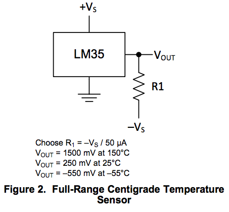
I'm looking to operate the LM35 in Full-Range (-55°C to 150°C). Figure 2 on page 1 of the datasheet (found here: http://www.ti.com/lit/ds/symlink/lm35.pdf) shows that a resistor must be added to the output of the LM35 in order for it to operate in Full-Range.
I'm confused as to what the other side of the resistor (labeled -Vs) should be connected to and how to figure out what size resistor I'll need being that I'm operating from a single supply. Also, what is the purpose of listing the different Vout ratings in this figure?
Here is Figure 2 from the datasheet:
Lastly, I just noticed Figure 18 on page 11 of the datasheet. Now I'm even more confused as to whether I should wire it up as shown in Figure 2 or Figure 18??? What's the difference between the two?
Figure 18:

Any help would be greatly appreciated.
I'm looking to use the Texas Instruments LM35 temperature sensor to (yes, you guessed it) monitor ambient temperature in a refrigerator.
The overall goal is to eliminate the existing Temperature Control Knob and replace it with an Arduino controlled/triggered Solid State Relay. This will also allow me to have an LCD readout of the temperature and be able to "dial in" a Set/Desired Temperature via programming or some other source such as a potentiometer.
I'm looking to operate the LM35 in Full-Range (-55°C to 150°C). Figure 2 on page 1 of the datasheet (found here: http://www.ti.com/lit/ds/symlink/lm35.pdf) shows that a resistor must be added to the output of the LM35 in order for it to operate in Full-Range.
I'm confused as to what the other side of the resistor (labeled -Vs) should be connected to and how to figure out what size resistor I'll need being that I'm operating from a single supply. Also, what is the purpose of listing the different Vout ratings in this figure?
Here is Figure 2 from the datasheet:
Lastly, I just noticed Figure 18 on page 11 of the datasheet. Now I'm even more confused as to whether I should wire it up as shown in Figure 2 or Figure 18??? What's the difference between the two?
Figure 18:
Any help would be greatly appreciated.
")


